Multi-layer blow molding device

A technology of blow molding and blow molding, which is applied in the field of multi-layer blow molding devices, which can solve the problems of central point misalignment, waste, and low efficiency of equipment, and achieve the effect of easy docking and separation

Pending Publication Date: 2020-09-22
杭州富阳鑫腾塑料制品有限公司
View PDF0 Cites 0 Cited by
  • Summary
  • Abstract
  • Description
  • Claims
  • Application Information

AI Technical Summary

Problems solved by technology

[0004] The purpose of the present invention is to provide a multi-layer blow molding device to solve the problem that the connection of the existing blow molding device proposed in the above background technology will cause liquid leakage due to insufficient butt joint during blow molding. When the mold of the blow molding device is withdrawn and replaced, the injection port will continue to leak and cause waste. The existing blow molding device only has one mold for processing, which leads to low working efficiency of the equipment. The existing blow molding device only has one mold for processing. It can fix small-scale molds, which affects the adaptability of the equipment. When the existing blow molding device replaces molds of different sizes, the center point will not be aligned, which will easily lead to problems in the blow molding effect of the equipment.

Method used


Image

  • Multi-layer blow molding device
  • Multi-layer blow molding device
  • Multi-layer blow molding device

Examples


Embodiment Construction

[0027] The following will clearly and completely describe the technical solutions in the embodiments of the present invention with reference to the accompanying drawings in the embodiments of the present invention. Obviously, the described embodiments are only some, not all, embodiments of the present invention.

[0028] In the description of the present invention, unless otherwise stated, the meaning of "plurality" is two or more; the terms "upper", "lower", "left", "right", "inner", "outer" , "front end", "rear end", "head", "tail", etc. indicate the orientation or positional relationship based on the orientation or positional relationship shown in the drawings, and are only for the convenience of describing the present invention and simplifying the description, rather than Nothing indicating or implying that a referenced device or element must have a particular orientation, be constructed, and operate in a particular orientation should therefore not be construed as limiting ...


PUM


Abstract

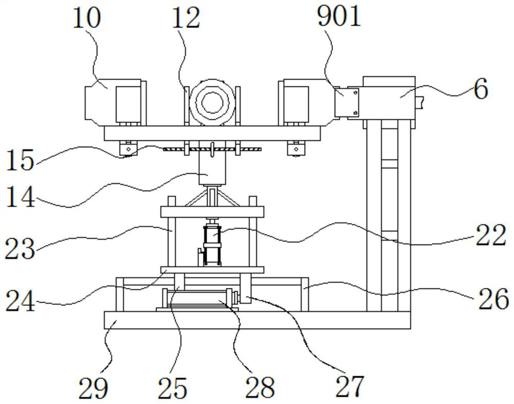
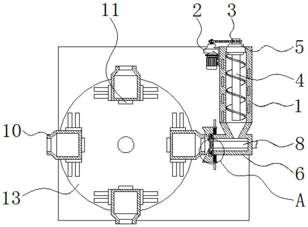
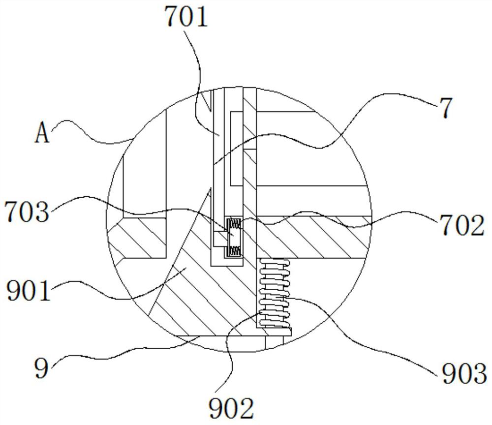
The invention relates to a multi-layer blow molding device. The device comprises a conveying shell, blow molding molds and a support, wherein a first motor is arranged on the left side of the conveying shell, a screw rod is arranged on the right side of a chain, an injection molding port is fixed in front of the conveying shell, an air blowing port is fixed in the injection molding port, the blowmolding molds are located on the left sides of port sealing mechanisms, and clamping plates are arranged on the front sides and the rear sides of the blow molding molds. The multi-layer blow molding device has the beneficial effects that the liquid leakage at a connection port in the injection molding process of the device is prevented through a sealing mechanism; the waste caused by continuous leakage of the injection molding port in the mold replacement process of the device is prevented through the port sealing mechanisms; the device can continuously replace the molds through a second motorso that the device can work in a multi-layer mode; the molds of various specifications can be clamped and fixed through a two-way threaded rod, and meanwhile, feeding ports of the molds can be located in the same position; and the situation that the butt joint of the device is affected due to angle changes of the device can be prevented through second guide rods.

Description

technical field [0001] The invention relates to the technical field of blow molding devices, in particular to a multilayer blow molding device. Background technique [0002] Blow molding, here mainly refers to hollow blow molding (also known as blow molding) is a method of blowing the hot-melt parison closed in the mold to form a hollow product by means of gas pressure, and is the third most commonly used plastic processing method. , is also a fast-growing plastic molding method. The mold for blow molding only has a female mold (concave mold). Compared with injection molding, the equipment cost is lower, the adaptability is stronger, and the formability is good (such as low stress ), products with complex undulating curves (shape) can be formed. [0003] The connection of the existing blow molding device will cause liquid leakage due to insufficient butt joint during blow molding. The injection port of the existing blow molding device will continue to leak liquid when the m...

Claims


Application Information

Patent Timeline
IPC IPC(8): B29C49/06B29C49/22B29C49/42B29C49/48B29C49/58
CPCB29C49/06B29C49/22B29C49/42B29C49/48B29C49/58B29C2049/023
Inventor 徐良
Owner 杭州富阳鑫腾塑料制品有限公司
Why Eureka
Try Eureka