Lubricating oil supply structure

A lubricating oil and structure technology, applied in the direction of pressure lubricant, lubricating parts, valve accessories, etc., can solve the problems of increased mechanical loss, increased oil pump capacity, and worsened fuel economy, and achieve the effect of reducing flow

Pending Publication Date: 2020-09-22
TOYOTA JIDOSHA KK
View PDF8 Cites 0 Cited by
  • Summary
  • Abstract
  • Description
  • Claims
  • Application Information

AI Technical Summary

Problems solved by technology

[0002] It is known that from the viewpoint of preventing clogging by foreign matter, the oil passage for supplying lubricating oil cannot usually be smaller than about φ1.2-1.5mm
In this case, if the diameter of the oil passage is increased to prevent clogging by foreign matter, more than the required amount of lubricating oil will be supplied to the parts (parts requiring lubrication) that can slide without problems even with a small amount of lubricating oil, so the capacity of the oil pump will increase. Large, mechanical loss increases, and fuel economy may deteriorate

Method used


Image

  • Lubricating oil supply structure
  • Lubricating oil supply structure
  • Lubricating oil supply structure

Examples


no. 1 approach

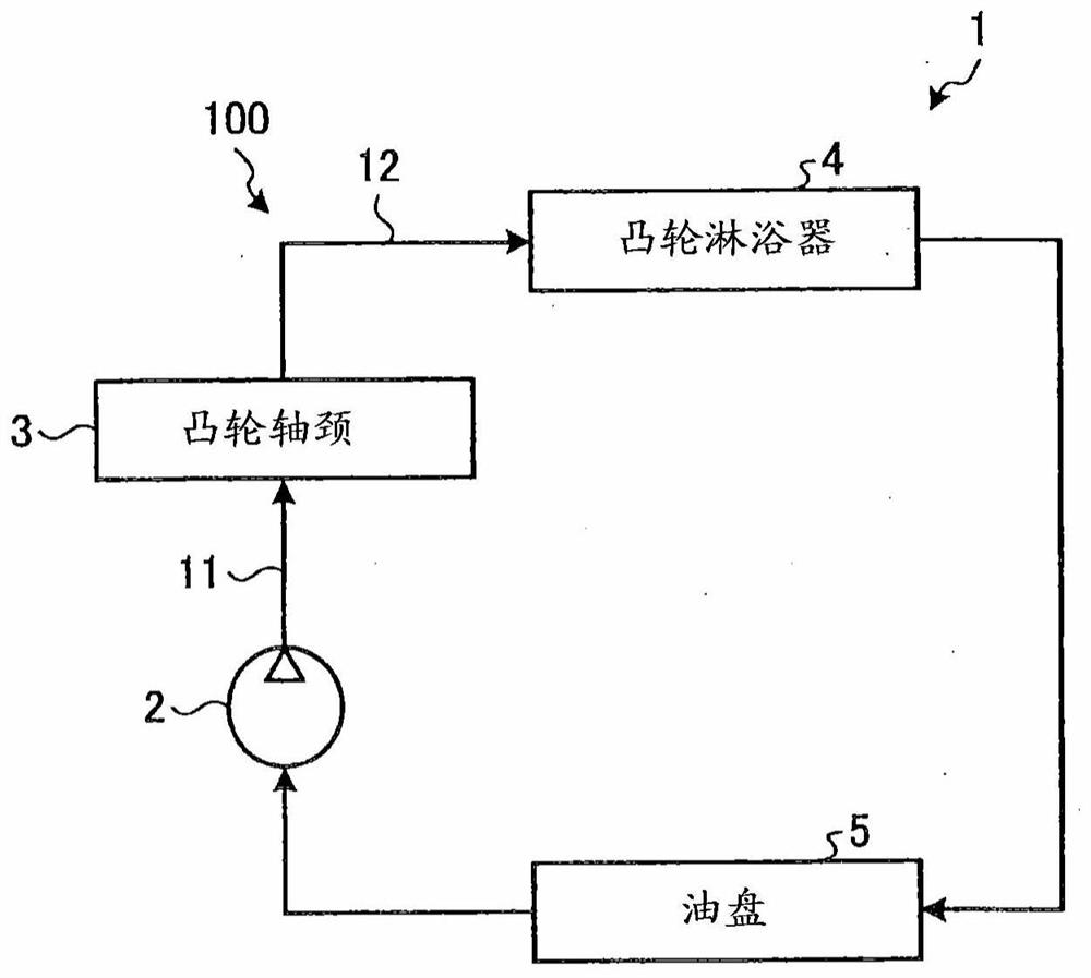
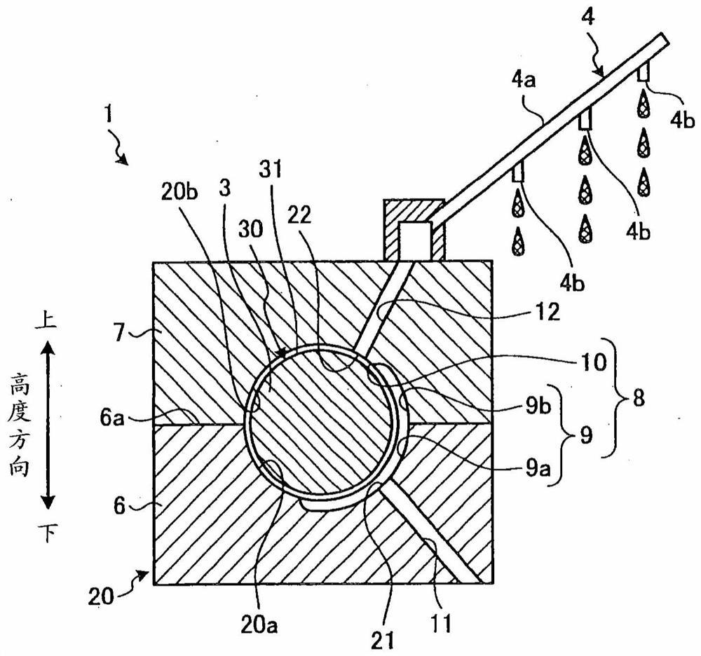
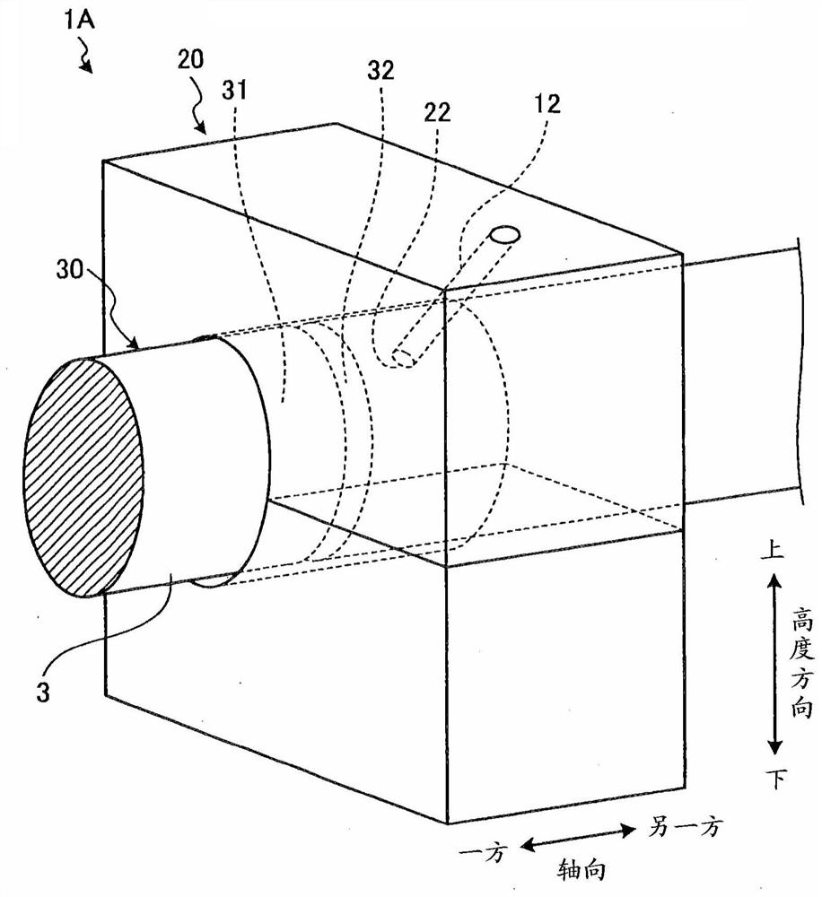
[0053] figure 1 It is a configuration diagram showing a case where the lubricating oil supply structure in the first embodiment is applied to a lubricating device for an internal combustion engine. figure 2 It is a schematic diagram which shows the schematic structure of the lubricating oil supply structure in 1st Embodiment.

[0054] The lubricating oil supply structure 1 in the first embodiment can be applied to a lubricating device 100 for an internal combustion engine. Such as figure 1 As shown, a lubricating device 100 for an internal combustion engine is a device that circulates lubricating oil using an oil pump 2 , and supplies lubricating oil to a cam journal 3 and a cam shower 4 . The supply destinations of lubricating oil include the cam journal 3 and the cam shower 4 . In this circulation path, a cam shower 4 is arranged on the downstream side of the cam journal 3 . Cam Shower 4 is where a small amount of lube is enough to get the required amount.

[0055] The...

no. 2 approach

[0082] Figure 8 It is a configuration diagram showing a case where the lubricating oil supply structure in the second embodiment is applied to a lubricating device for an internal combustion engine. Figure 9 It is a schematic diagram which shows the schematic structure of the lubricating oil supply structure in 2nd Embodiment. Figure 10 It is a schematic diagram which shows the schematic structure of the lubricating oil supply structure in 2nd Embodiment. exist Figure 10 , schematically illustrates the representation Figure 9 Cutaway view of the C-C line section. In addition, in description of 2nd Embodiment, description is abbreviate|omitted about the structure similar to 1st Embodiment mentioned above, and the code|symbol is used.

[0083] Such as Figure 8 As shown, in the lubricating device 100 of the second embodiment, the oil pumped from the oil pump 2 is supplied to the crankshaft 51 and the oil injection nozzle 52 . Destinations of lubricating oil supply inc...


PUM


Abstract

The invention provides a lubricating oil supply structure capable of suppressing foreign matter clogging with a simple structure and reducing the flow rate of lubricating oil supplied to a part requiring lubrication. This lubricating oil supply structure (1) is provided with: an oil supply port (21) that is provided to a bearing section (20) that supports a camshaft (30) and supplies lubricating oil between the bearing section and the camshaft; a first oil passage (11) through which the lubricating oil supplied from the oil pump flows to the oil supply port; an introduction port (22) into which lubricating oil present between the bearing part and the camshaft (30) is introduced; and a second oil passage (12). The lubricating oil introduced from the introduction port is supplied to a supplydestination different from the bearing part. The lubricating oil supply structure is provided with a connecting oil passage (8) which is formed by a gap between the bearing part and the camshaft andconnects the first oil passage and the second oil passage, and a throttle part (10) which suppresses the flow of lubricating oil from the oil supply port to the inlet is provided in the connecting oilpassage.

Description

technical field [0001] The present invention relates to a lubricating oil supply structure. Background technique [0002] From the viewpoint of preventing clogging by foreign matter, it is known that the oil passage for supplying lubricating oil cannot usually be smaller than about φ1.2 to 1.5 mm. In this case, if the diameter of the oil passage is increased to prevent clogging by foreign matter, more than the required amount of lubricating oil will be supplied to the parts (parts requiring lubrication) that can slide without problems even with a small amount of lubricating oil, so the capacity of the oil pump will increase. Large, the mechanical loss increases, and fuel economy may worsen. Therefore, it is desirable to reduce the amount of lubricating oil to be supplied according to the amount required by the supply destination of the lubricating oil (site requiring lubrication). [0003] Patent Document 1 discloses that lubricating oil is supplied from an oil pump to an ...

Claims


Application Information

Patent Timeline
IPC IPC(8): F01M1/06F01M1/16F01M9/10F01M1/02
CPCF01M1/06F01M1/16F01M9/10F01M9/101F01M9/102F01M1/02F01M2001/064F01L1/053F01L2001/0476F01L2810/02F01L2820/01F02F7/0053F01M2011/026F01M11/02F01M9/105F01M1/12F01L1/047
Inventor 小山崇
Owner TOYOTA JIDOSHA KK
Why Eureka
Try Eureka