Device for testing high and low temperature resistance of integrated circuit

An integrated circuit, high and low temperature resistant technology, applied in the field of integrated circuit temperature resistance detection device, can solve problems such as poor start-up of integrated circuits, impact of detection of integrated circuits to be tested, and impact on the service life of integrated circuits

Inactive Publication Date: 2020-09-22
杭州很美网络科技有限公司
View PDF0 Cites 4 Cited by
  • Summary
  • Abstract
  • Description
  • Claims
  • Application Information

AI Technical Summary

Problems solved by technology

[0004] There are many indicators of the working environment of integrated circuits, such as operating temperature and humidity. Excessively high temperature will cause the integrated circuit to work under high temperature overload, which will easily cause fatigue damage to the integrated circuit and affect the service life of the integrated circuit. It will cause the integrated circuit to start poorly, easily cause the integrated circuit to fail, and affect the normal work
[0005] Therefore, in the process of integrated circuit design, for some integrated circuits with special needs (such as extreme climate use, or large temperature difference in the use environment), the performance of high and low temperature resistance is usually tested. Most of the existing test devices are disassembled. Installed, the test device needs to be disassembled every time the integrated circuit to be tested is installed and replaced, but as a result, the connection between the various parts of the disassembled test device is prone to loosening, resulting in low overall sealing performance and difficult heat preservation. detection of ICs that affect the detection of

Method used


Image

  • Device for testing high and low temperature resistance of integrated circuit
  • Device for testing high and low temperature resistance of integrated circuit
  • Device for testing high and low temperature resistance of integrated circuit

Examples


Embodiment 1

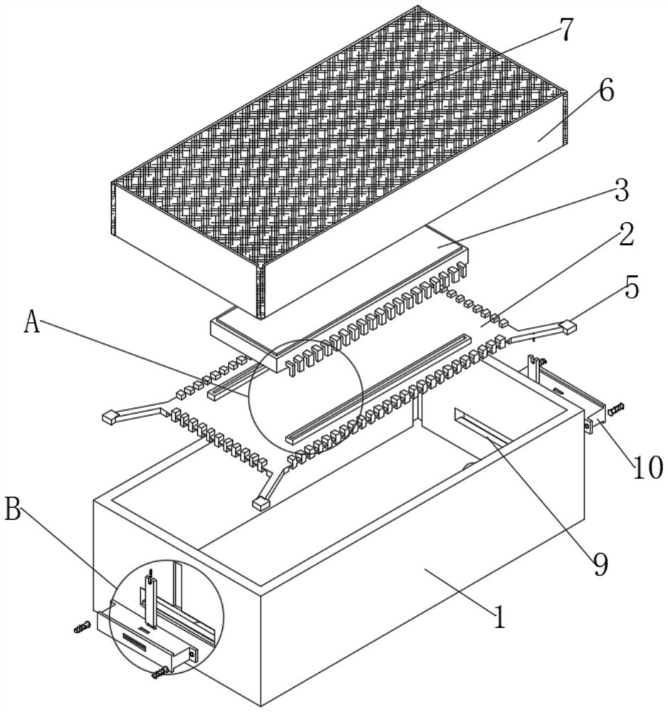
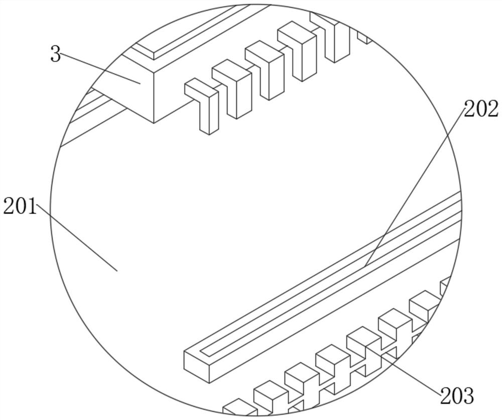
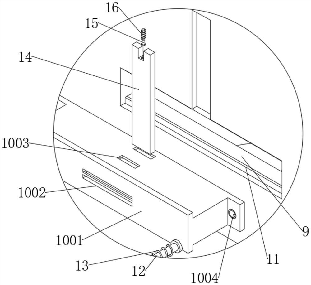
[0036] See Figure 1-2 , A device for high and low temperature resistance testing of integrated circuits, including a detection box 1. The bottom of the groove of the detection box 1 is drilled with a mounting slot, and a temperature change device 8 matching itself is fixedly connected to the mounting slot. A detection circuit board 2 that matches with itself is placed. Multiple sets of electric slide rails 4 are excavated on the side wall of the detection box 1. The multiple sets of electric slide rails 4 are all located at the corners of the detection box 1, and the detection circuit board 2 is fixed A plurality of electric sliders 5 matched with the electric slide rail 4 are connected. The detection box 1 and the detection circuit board 2 are connected by the electric slide rail 4 and the electric slider 5 to achieve a sliding connection. The upper side of the detection circuit board 2 is provided The integrated circuit main body 3, the detection circuit board 2 includes a d...


PUM


Abstract

The invention discloses a device for testing high and low temperature resistance of an integrated circuit. The invention belongs to the field of integrated circuit temperature resistance detection devices. According to the scheme, the size of the detection box is greatly reduced; the influence volume required by the temperature change device is reduced; the overall temperature in the detection boxis easy to control; a closed space formed by entanglement of a plurality of elastic fibers is formed in the heat preservation curtain at the upper half part of the detection box, so that air in the detection box can be effectively isolated from heat exchange with air outside the detection box; meanwhile, normal penetration of the detection circuit board and the integrated circuit main body through the heat preservation curtain is not influenced; the thermal insulation curtain is composed of a plurality of groups of elastic fibers with different trunk directions, so that mutual complementationcan be realized, the thermal insulation effect of the thermal insulation curtain is greatly improved, the detection device does not need to be disassembled when an integrated circuit to be detected is changed, connection between all parts of the detection device is not easy to loosen, and thermal insulation is easy to carry out.

Description

Technical field [0001] The invention relates to the field of integrated circuit temperature resistance detection devices, and more specifically, to a device used for high and low temperature resistance testing of integrated circuits. Background technique [0002] Integrated circuit (integrated circuit) is a kind of miniature electronic device or component. A certain process is used to interconnect the transistors, resistors, capacitors, inductors and other components and wiring required in a circuit, fabricate them on a small or several small semiconductor chips or dielectric substrates, and then package them in a package , It has become a microstructure with the required circuit functions; all of the components have been structured as a whole, making electronic components a big step towards microminiaturization, low power consumption, intelligence and high reliability. [0003] Now, integrated circuits have played a very important role in all walks of life and are the cornerstone...

Claims


Application Information

Patent Timeline
Patent Type & Authority Applications(China)
IPC IPC(8): G01R31/28
CPCG01R31/2862G01R31/2877
Inventor 李娟
Owner 杭州很美网络科技有限公司
Why Eureka
Try Eureka