Method for detecting current peak position of switched reluctance motor

A technology of switched reluctance motor and current peak value, applied in the direction of control of electromechanical transmission, control of generator, motor-generator control, etc., can solve the problems of speed fluctuation, large influence, motor running vibration, etc. change-sensitive effects

Active Publication Date: 2020-09-22
DALIAN UNIV OF TECH
View PDF7 Cites 8 Cited by
  • Summary
  • Abstract
  • Description
  • Claims
  • Application Information

AI Technical Summary

Problems solved by technology

However, in the actual control, the current peak position is affected by many factors, resulting in the current peak value not appearing at the position where the salient poles of the motor stator and rotor just overlap, making the detection results inaccurate, and the resulting position detection error greatly reduces the control performance of the motor, resulting in There may be problems such as vibration and torque ripple during the operation of the motor
[0003] Because the current peak position of the switched reluctance motor is greatly affected by factors such as speed, current, opening angle, and DC bus voltage, and in the actual control process, due to many factors such as the structure of the motor, friction, and the delay of the double closed-loop PI control, etc. , even when the motor is running stably, the speed will still fluctuate, resulting in obvious fluctuations in the current peak position, which cannot be accurately detected. Therefore, it is necessary to invent a method that can accurately detect the current peak position under different operating conditions of the switched reluctance motor. The control method to make the motor run stably

Method used


Image

  • Method for detecting current peak position of switched reluctance motor
  • Method for detecting current peak position of switched reluctance motor
  • Method for detecting current peak position of switched reluctance motor

Examples


Embodiment Construction

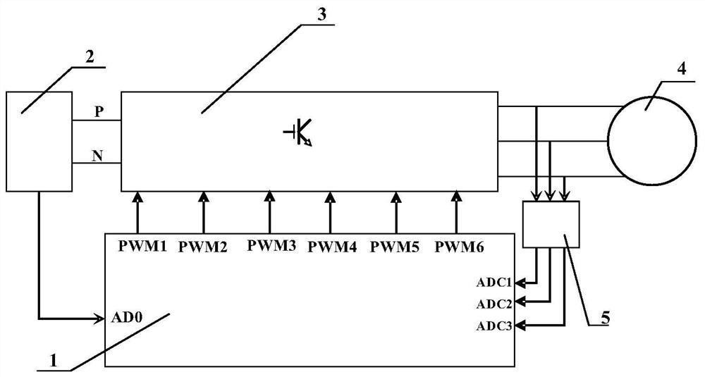
[0027] The specific embodiment of the present invention is as figure 1 As shown, the microcontroller 1 is the DSP chip TMS320F28069 of TI Company, the three-phase rectification and filtering circuit and its bus voltage detection circuit 2 detect the DC bus voltage U of the power converter 3, and input it to the microcontroller 1 after conditioning The ADC0 port of the power converter 3 adopts a three-phase asymmetrical half-bridge structure. The switched reluctance motor 4 is a three-phase switched reluctance motor with 12 / 8 poles, the rated power is 5kW, and the rated speed is 2000r / min. The current is input to the ADC1 port, ADC2 port and ADC3 port of the microcontroller 1 respectively.

[0028] The switched reluctance motor system adopts the traditional speed and current double closed-loop control without braking for a period of time after the start of power-on operation. The bus voltage detection circuit 2 detects the motor DC bus voltage of the power converter 3, and the...


PUM


Abstract

The invention provides a method for detecting a current peak position of a switched reluctance motor, and belongs to the field of rotor position detection of switched reluctance motors. According to the method, only the phase current and the phase voltage of the running motor need to be detected, and position sensors and other devices do not need to be additionally arranged. In the control process, when it is detected that the phase current of the motor has a peak value, the phase inductance value of the motor at the moment is calculated through the current and voltage of the motor, the phaseinductance value is multiplied by the ratio coefficient, which is obtained through simulation, of the rotor position and the inductance value of the motor at the rotating speed, and then the rotor position of the motor at the current peak value moment can be calculated. The method has the characteristics that the problem of current peak position fluctuation in the operation process of the motor can be solved, and the detection is sensitive; the problems of large occupied memory and inaccurate data due to the fact that a traditional table look-up method needs to aim at the influence of variousfactors are solved; and the method is more sensitive to different operation parameter changes of the motor and higher in detection precision.

Description

technical field [0001] The invention belongs to the field of switched reluctance motors, and relates to a precise rotor position detection and precise control method of a switched reluctance motor, which is mainly aimed at improving the detection accuracy of the current peak position when the phase current gradient method is used to detect the motor rotor position. Background technique [0002] Switched reluctance motors are widely used in many industries and industrial fields because of their simple structure, high power factor, small starting current, large starting torque, wide speed range, high operating efficiency and frequent start and stop. to go. The rotor position information needs to be known during the motor control operation process. Although traditional mechanical position sensors such as resolvers and photoelectric encoders can obtain more accurate motor rotor positions, they increase the operating cost of the motor, and the detection accuracy is affected by th...

Claims


Application Information

Patent Timeline
IPC IPC(8): H02P21/14H02P21/18
CPCH02P21/14H02P21/18
Inventor 孙建忠王岩白凤仙
Owner DALIAN UNIV OF TECH
Why Eureka
Try Eureka