
A laser surface processing method and system

A surface processing and laser technology, used in metal processing equipment, laser welding equipment, manufacturing tools, etc., can solve the problems of inability to dynamically adjust parameters, single effect style, etc., to reduce processing costs, improve system value, and avoid breakage. Effect

Active Publication Date: 2022-03-25
青岛自贸激光科技有限公司
View PDF13 Cites 0 Cited by
  • Summary
  • Abstract
  • Description
  • Claims
  • Application Information

AI Technical Summary

Problems solved by technology

[0003] Therefore, when the traditional laser processing system processes the material surface, the spot parameters are set before processing, and the scanning path in the processing pattern is sent to the galvanometer system through a control system, and the galvanometer system scans until the processing pattern is drawn. The parameters cannot be dynamically adjusted during the movement, and the effect style processed by this method is relatively simple

Method used


Image

  • A laser surface processing method and system
  • A laser surface processing method and system
  • A laser surface processing method and system

Examples


specific Embodiment 1

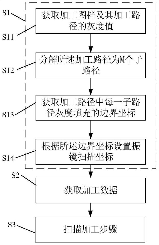
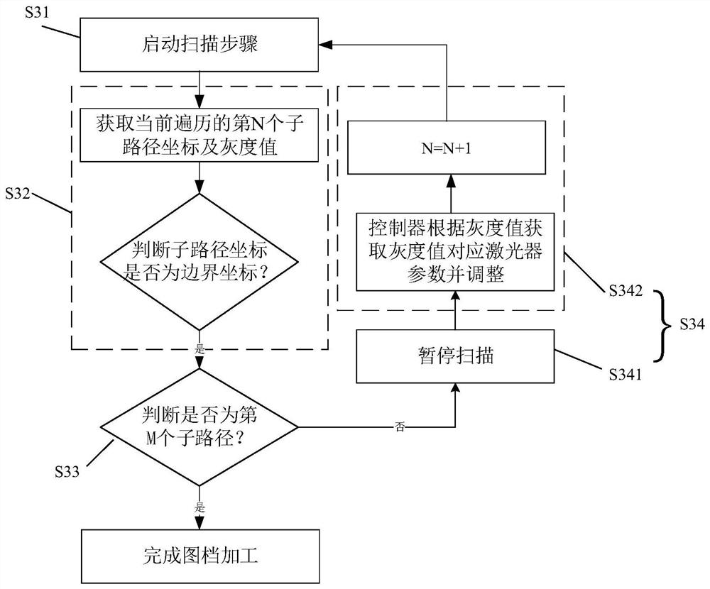
[0050] on the one hand, figure 1 It is a schematic schematic diagram of the preferred flow of the embodiment of the present invention, figure 2 It is a schematic flow chart of the preferred scanning processing steps in the embodiment of the present invention, refer to Figure 1-2 As shown, the present invention discloses a laser surface processing method, comprising:

[0051] The processing map file decomposition step S1 is to obtain the processing map file and decompose the processing path of the processing map file into a plurality of sub-paths according to the gray value, and obtain the gray-scale filled boundary coordinates of each sub-path, and at the same time set the vibration value according to the boundary coordinates. mirror scan coordinates;

[0052] The step S2 of acquiring the processing data is used for the grayscale laser parameter index table in the processing drawing file, wherein the grayscale laser parameter index table is established when the processing ...

specific Embodiment 2

[0073] Only the differences between this embodiment and the specific embodiment 1 will be described below, and the similarities will not be repeated.

[0074] This embodiment considers that in practical applications, the laser cannot completely correspond to all grayscale values, and the value range of the grayscale values ​​is (0, 249), so as to further reduce the amount of data in the processing process.


PUM


Abstract

The present invention proposes a method and system for laser surface processing, including: a step of decomposing a processing map file, obtaining a processing map file and decomposing the processing path of the processing map file into a plurality of sub-paths according to the gray value, and obtaining each sub-path The boundary coordinates of the grayscale filling, and the galvanometer scanning coordinates are set according to the boundary coordinates; the step of obtaining processing data is used for the grayscale laser parameter index table in the processing image file, wherein the grayscale laser parameter index table Including at least the grayscale value of the processing image file and its corresponding laser parameters; the scanning processing step dynamically adjusts the laser parameters corresponding to each sub-path according to the gray-scale laser parameter index table, and scans each sub-path in turn until the image is completed. file processing. By adopting the laser surface processing method and system of the above scheme, the parameters of the laser are dynamically adjusted during the laser processing, so that the processing effect has diversity and flexibility.

Description

technical field [0001] The invention belongs to the technical field of laser processing, and in particular relates to a method and system for dynamically regulated laser surface processing. Background technique [0002] Traditional laser surface processing systems generally use galvanometers to control the moving direction of the spot. In most cases, the same spot parameters are used for the movement path of a single spot, and even the same parameters are used in the entire processing process when processing some special patterns. [0003] Therefore, when the traditional laser processing system processes the material surface, the light spot parameters are set before processing, and the scanning path in the processing pattern is sent to the galvanometer system through a control system, and the galvanometer system scans until the processing pattern is drawn. The parameters cannot be dynamically adjusted during the moving process, and the effect style processed by this method i...

Claims


Application Information

Patent Timeline
Patent Type & Authority Patents(China)
IPC IPC(8): B23K26/082B23K26/70
CPCB23K26/082B23K26/702
Inventor 彭胜峰刘强陈强李德荣
Owner 青岛自贸激光科技有限公司
Learn More