Optical fiber optofluidic dye laser

A dye laser and optical fluid technology, applied in the optical field, can solve the problems affecting the use range and application flexibility of the light source, the laser output beam mode is not adjustable, the optical resonator structure is not adjustable, etc. Flexibility, output beam pattern controllable effects

Inactive Publication Date: 2014-09-10
高秀敏
View PDF0 Cites 3 Cited by
  • Summary
  • Abstract
  • Description
  • Claims
  • Application Information

AI Technical Summary

Problems solved by technology

This laser has considerable advantages, but there are still some essential deficiencies: 1) The system uses optical gratings to form feedback, and optical gratings are built in three-dimensional optical waveguides to form a distributed feedback system, and then form an optical resonant cavity, all of which are microscopic structures , which essentially makes the system have high requirements on the preparation process, the process of preparing the laser is complicated, difficult, and the whole system is complicated; 2) The pumping method in the prior art is a paraxial asymmetric pump, and the side of the pump beam Irradiating to the optical gain region and the region containing dye molecules affects the uniformity of the pumping effect, and the entire stimulated radiation system has asymmetry, which affects the quality of the laser output beam. At the same time, the utilization rate of the pumping light energy is low; 3) Once the optical microstructure in the system is formed, it cannot be changed, and the structure of the optical resonant cavity cannot be adjusted. In this way, the mode of the output beam of the laser cannot be adjusted, which affects the use range and application flexibility of the light source.

Method used


Image

  • Optical fiber optofluidic dye laser

Examples


Embodiment Construction

[0018] The present invention will be described in further detail below in conjunction with the accompanying drawings.

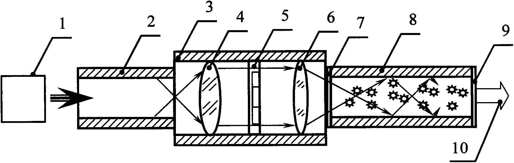
[0019] like figure 1 Shown is a schematic diagram of the structure of a fiber optofluidic dye laser according to an embodiment of the present invention, which is a rotationally symmetrical structure, and a pumping light source 1, a pumping fiber 2, and a light beam are sequentially arranged on the optical path of the incident pumping beam on the same optical axis. Shaping device 3, first reflector 7, dye hollow-core fiber 8, second reflector 9; first reflector 7, dye hollow-core fiber 8 and second reflector 9 form a resonant cavity, and the resonant cavity is provided with laser The dye of the gain medium; the beam shaping device 3 is sequentially provided with a collimating lens 4, a phase adjuster 5 and a converging lens 6 in the direction of propagation of the pumping beam, and the collimating lens 4 collimates the outgoing beam of the pumping optical fibe...


PUM


Abstract

The invention discloses an optical fiber optofluidic dye laser. The optical fiber optofluidic dye laser comprises a pump optical source, a pumping optical fiber, a first reflecting mirror, a dye hollow-core optical fiber and a second reflecting mirror which are connected with one another in sequence are arranged along a light beam emitting direction of the pump optical source, dye in sealed space which is formed by the first reflecting mirror, the dye hollow-core optical fiber and the second reflecting mirror serves as a laser gain medium, and a light beam shaping device which is used for adjusting wavefront phase positions of pump light beams is mounted between the pumping optical fiber and the first reflecting mirror. The optical fiber optofluidic dye laser has advantages of existing optofluidic lasers, and meanwhile, has the advantages that the system structure is simple, the miniaturization degree is high, the preparation technology is simple, axial symmetry optical pumping is achieved, the pumping optical energy utilizing ratio is high, the application range is wide, qualities of the light beams are good, output beam modes are controllable, the usage is flexible, and the like.

Description

technical field [0001] The invention belongs to the field of optical technology, and relates to a laser, especially a fiber optic fluid dye laser, which is mainly used for laser measurement, laser processing, laser marking, laser welding, laser guidance, laser medicine, spectrum technology, optical fiber communication, It can be used as a laser light source in the fields of wireless optical communication, optical micromanipulation, optical microscopy, and the interaction between light and matter. Background technique [0002] A laser is a device that uses the principle of stimulated radiation to amplify or oscillate light in certain excited substances. At present, there are many kinds of lasers, and the common ones are gas lasers, solid-state lasers, liquid lasers, and semiconductor lasers. The working principles of various lasers are basically the same. The indispensable conditions for generating laser light are particle number reversal and large gain over loss. Therefore,...

Claims


Application Information

Patent Timeline
Patent Type & Authority Applications(China)
IPC IPC(8): H01S3/20H01S3/10
Inventor 姜利平李楠张宇高秀敏
Owner 高秀敏
Why Eureka
Try Eureka