
Method and system for automatically leading and gumming shoe uppers

An automatic guidance and gluing technology, which is applied in the direction of program control manipulators, instruments, calculations, etc., can solve problems such as difficulty in ensuring accuracy and difficulty in obtaining gluing path lines, and achieves improved accuracy and consistency, low requirements, and operator requirements. low effect

Active Publication Date: 2020-09-25
ZHEJIANG CORNERSTONE INTELLIGENT TECH CO LTD
View PDF11 Cites 8 Cited by
  • Summary
  • Abstract
  • Description
  • Claims
  • Application Information

AI Technical Summary

Problems solved by technology

[0005] This application provides a method and system for automatically guiding gluing on the upper surface, which solves the problems in the prior art that the gluing path line is difficult to obtain and the accuracy is difficult to guarantee, and realizes the simplification and high efficiency of the gluing path line acquisition process. Simultaneously improves glue path accuracy and consistency

Method used


Image

  • Method and system for automatically leading and gumming shoe uppers
  • Method and system for automatically leading and gumming shoe uppers
  • Method and system for automatically leading and gumming shoe uppers

Examples


Embodiment 1

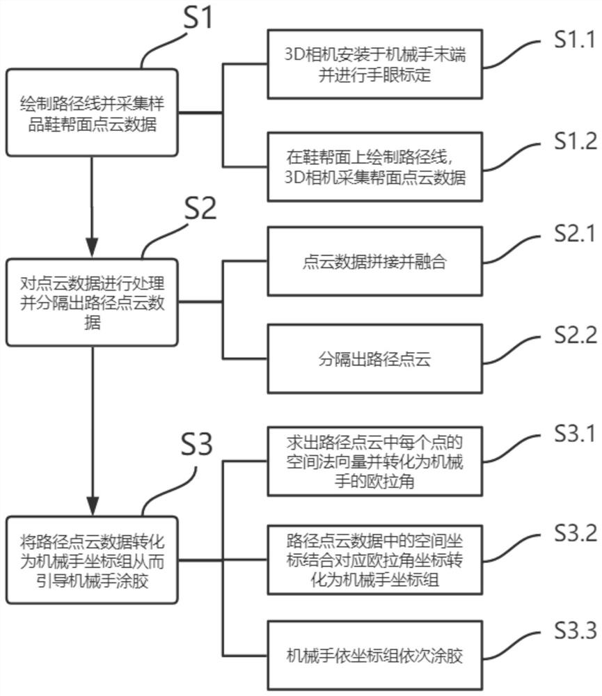
[0042] like figure 1 As shown, a method for automatically guiding gluing on the upper surface, which specifically includes the following steps:

[0043] S1.1, the image acquisition device selects a 3D camera, installs the 3D camera at the end of the manipulator, and performs hand-eye calibration to determine the homogeneous transformation relationship of the 3D camera relative to the end of the manipulator. The hand-eye calibration method is as follows:

[0044] Rotate the camera to take a fixed cone each time, then the formula is as follows:

[0045] T i ·X·m i =T j ·X·m j (l);

[0046] T in formula (1) i is a 4x4 homogeneous change matrix, indicating the attitude of the end of the manipulator at the i-th time, X is a 4x4 homogeneous change matrix, indicating the installation relationship between the camera and the end of the manipulator, the installation relationship is a fixed value, m i is a 4x1 column vector, which represents the coordinate value of the cone in th...

Embodiment 2

[0092] Embodiment two: a kind of gluing system that adopts the gluing method described in embodiment one, comprising:

[0093] Manipulator, used to automatically apply glue to the upper surface of the shoe;

[0094] A 3D camera that can collect grayscale or RGB information is installed at the end of the manipulator, and the image collection device is used to collect point cloud data of the upper surface of the sample;

[0095] The processors are respectively electrically connected to the 3D cameras, and the processors receive and process point cloud data collected by the 3D cameras and generate a coordinate group that can be recognized by the manipulator.

[0096] The above-mentioned technical solutions in the embodiments of the present application have at least the following technical effects or advantages:

[0097] 1. This method pre-draws the path line on the upper surface, and then drives the image acquisition device to obtain the point cloud data of the sample upper surf...


PUM


Abstract

The invention discloses a method for automatically leading and gumming shoe uppers in the technical field of shoemaking. The method specifically comprises the following steps of S1, drawing a route line on a sample shoe upper surface in advance, and obtaining point cloud data through an image acquiring device mounted on a manipulator; S2, performing splicing fusion treatment on the point cloud data, and separating route point cloud data in the route line; and S3, transforming position information and space normal vector information in the route point cloud data into a manipulator xyzrpy coordination group to lead the manipulator to perform gumming. Through the adoption of the gumming method disclosed by the invention, the gumming route can be accurately identified, repeated attempting andverifying are not needed, the operation is simple and high in efficiency, requirements for operators are low, and besides, the gumming route is high in accuracy and high in consonance.

Description

technical field [0001] The invention relates to the technical field of shoemaking, in particular to a method and system for automatic guiding and gluing of uppers. Background technique [0002] In the boot leather processing and manufacturing industry, the current sole gluing process is mostly done manually, which is time-consuming and laborious and has uneven quality. In addition, this process involves a variety of media such as gas and liquid, and its variable performance makes the gluing process complicated. With the increasing requirements for green environmental protection and improving the working environment of laborers, this has continuously prompted manufacturers to try and use new technologies. It has been many years in the research and development of domestic robots, and its research results have been applied to actual production one after another. Therefore, it is imperative to introduce robot technology into the gluing process. The research and development of ...

Claims


Application Information

Patent Timeline
Patent Type & Authority Applications(China)
IPC IPC(8): B25J11/00B25J9/00B25J9/16B25J19/02G06K9/00G06K9/46
CPCB25J11/0075B25J9/0081B25J9/1664B25J9/1697B25J19/023G06V20/10G06V10/56
Inventor 阮春晖
Owner ZHEJIANG CORNERSTONE INTELLIGENT TECH CO LTD
Learn More