Dust removal system for rubber mixing mill

A technology of dust removal system and rubber mixing machine, which is applied in the direction of dust removal, cleaning methods and utensils, and dispersed particle filtration. Personal hazard, good filtering effect, easy to vacuum effect

Inactive Publication Date: 2020-09-25
河北汇海橡塑材料股份有限公司
View PDF11 Cites 0 Cited by
  • Summary
  • Abstract
  • Description
  • Claims
  • Application Information

AI Technical Summary

Problems solved by technology

[0005] The purpose of the present invention is to provide a dust removal system for a rubber mixing machine. The filter plate inside the dust removal chamber can filter small dust, and the filter plate set on the inclined surface has a large contact area with the air flow, and the filtering effect is good. The advanced cycle dust removal mechanism can wash the dust accumulated on the filter plate, so as to ensure the filtration efficiency of the filter plate. At the same time, a water cycle is set, and the dust will adhere to the filter plate when it encounters water, which enhances the filtering effect. In the prior art, although the existing dust removal system for the rubber mixer uses a dust removal tank for dust filtration and cleaning, it occupies a large space, and the primary sedimentation tank cannot be installed at the upper end of the rubber mixer, resulting in a mediocre dust removal effect. It is impossible to quickly eliminate the problem of dust generated by the rubber mixer during production and processing

Method used


Image

  • Dust removal system for rubber mixing mill
  • Dust removal system for rubber mixing mill
  • Dust removal system for rubber mixing mill

Examples


Embodiment 1

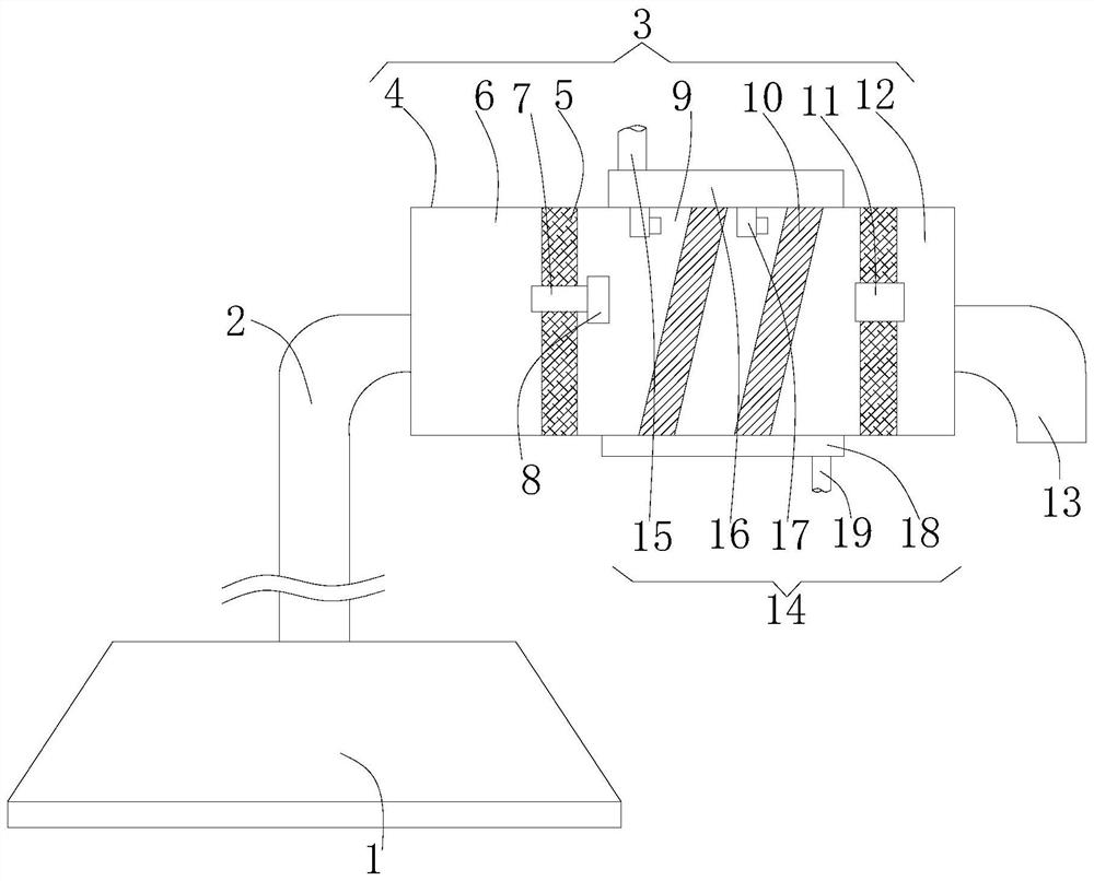
[0030] refer to Figure 1-6 Shown is the preferred embodiment provided by the present invention.

[0031] A dust removal system for a rubber mixing machine, comprising a dust cover 1, the top of the dust cover 1 is connected to a connecting pipe 2, and the end of the connecting pipe 2 is connected to a dust-proof mechanism 3, and the dust-proof mechanism 3 includes a box body 4, the box body Both sides of the box 4 are provided with partitions 5. The partitions 5 divide the interior of the box body 4 into a dust collection chamber 6, a dust removal chamber 9 and a purification chamber 12. On the partition 5 between the dust collection chamber 6 and the dust removal chamber 9 A first through pipe 7 is provided, and a plurality of filter plates 10 are arranged inside the dust removal chamber 9, and a circulation dust removal mechanism 14 is also arranged inside the dust removal chamber 9, and the circulation dust removal mechanism 14 and the interior of the dust removal chamber ...

Embodiment 2

[0038] The technical solution is: a dust suction tube 22 is arranged in the dustproof cover 1, an air outlet tube 24 is arranged on the upper side of the middle part of the dust suction tube 22, the end of the air outlet tube 24 is connected to the connecting pipe 2, and a threaded connection is provided at the bottom of the dust suction tube 22. Cylinder 25, the threaded connection cylinder 25 is directly connected with the rubber mixing machine through a connecting hose, the external device provides power, and the dust directly enters the interior of the dust suction cylinder 22 through the threaded connection cylinder 25.

[0039] The rest of the technical solutions are the same as those in Embodiment 1, and such setting makes the dust inside the rubber mixing machine directly discharged into the inside of the dustproof cover 1, thereby completely avoiding the possibility of flying dust.

[0040] In this embodiment, the entire operation process can be controlled by a compute...


PUM


Abstract

The invention relates to the technical field of rubber mixing mill dust removal, and discloses a dust removal system for a rubber mixing mill. The dust removal system comprises a dust cover, the top end of the dust cover is connected with a communicating pipe, the tail end of the communicating pipe communicates with a dust prevention mechanism, the dust prevention mechanism comprises a box body, and partition plates are arranged on the two sides in the box body; the partition plates divide the interior of the box body into a dust collection cavity, a dust removal cavity and a purification cavity, a first through pipe is arranged on the partition plate between the dust collection cavity and the dust removal cavity, a plurality of filter plates are arranged in the dust removal cavity, and acirculating dust removal mechanism is further arranged in the dust removal cavity. According to the dust removal system, the contact area between a filter plate arranged on the inclined plane and airflow is large, and the filtering effect is good; the arranged circulating dust removal mechanism can flush dust accumulated on the filter plate, and the filtering efficiency of the filter plate is guaranteed; and meanwhile, water circulation is arranged, the dust can be attached to the filter plate when meeting water, and the filtering effect is enhanced.

Description

technical field [0001] The patent of the present invention relates to the technical field of dust removal for rubber mixers, in particular, to a dust removal system for rubber mixers. Background technique [0002] Silica, the raw material in the rubber mixing workshop, is very easy to generate dust during its handling, feeding and rubber mixing process. The particle size of fumed silica is small (the particle size is generally 0.5-3μm, which belongs to ultrafine dust), and the specific surface area is large. , the filling density is small, it is easy to form floating dust, and the dust is easy to contaminate the bare skin and hair of the operator, causing the dryness of the skin and hair, which is easy to make the operator feel psychologically disgusted, and the dust is inhaled into the lungs, which may be harmful Human health, if the dust diffuses into the atmosphere without control, it may have a serious impact on the surrounding environment. [0003] After searching, the...

Claims


Application Information

Patent Timeline
Patent Type & Authority Applications(China)
IPC IPC(8): B29B7/80B29B7/84B01D46/00B01D46/12B01D53/04B08B15/04
CPCB29B7/80B29B7/84B01D46/12B01D53/04B08B15/04B01D46/681
Inventor 谌凡
Owner 河北汇海橡塑材料股份有限公司
Why Eureka
Try Eureka