Cooling Of Rotor And Stator Components Of A Turbocharger Using Additively Manufactured Component-Internal Cooling Passages

A turbocharger and additive manufacturing technology, which is applied to the components, stators, and manufacturing of pumping devices for elastic fluids. Effects of improved cooling and improved compression efficiency

Inactive Publication Date: 2020-09-25
MAN ENERGY SOLUTIONS SA
View PDF0 Cites 0 Cited by
  • Summary
  • Abstract
  • Description
  • Claims
  • Application Information

AI Technical Summary

Problems solved by technology

The disadvantage of these cooling concepts for turbochargers is that, on the one hand, the high thermal load on the turbocharger components and, on the other hand, further efficiency optimization of these components is not possible

Method used


Image

  • Cooling Of Rotor And Stator Components Of A Turbocharger Using Additively Manufactured Component-Internal Cooling Passages
  • Cooling Of Rotor And Stator Components Of A Turbocharger Using Additively Manufactured Component-Internal Cooling Passages
  • Cooling Of Rotor And Stator Components Of A Turbocharger Using Additively Manufactured Component-Internal Cooling Passages

Examples


Embodiment Construction

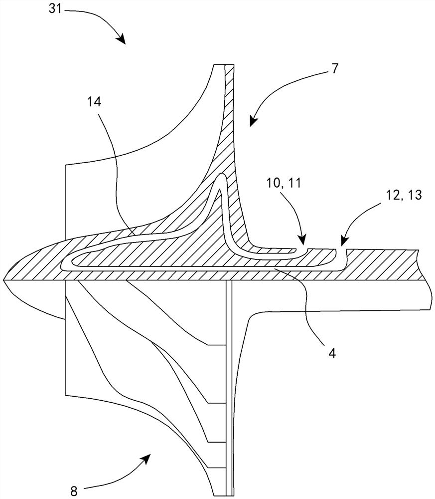
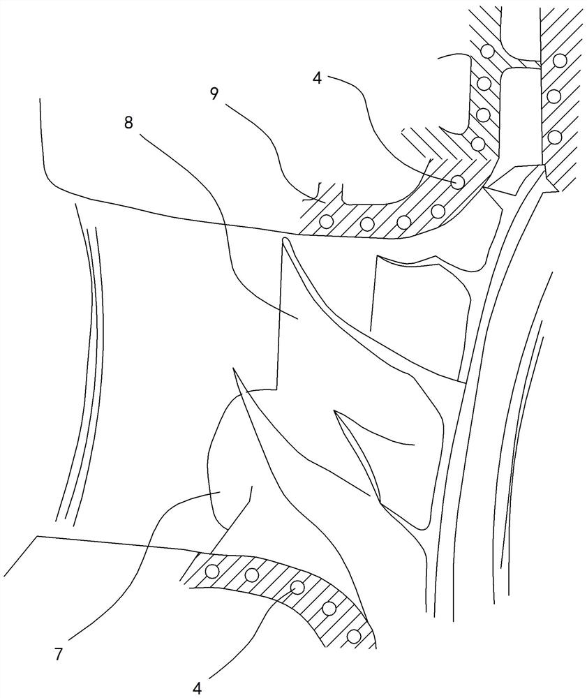
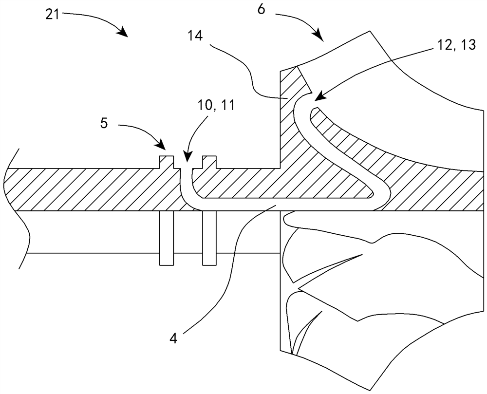
[0040] exist figure 1 , a cross-sectional view of a rotor 21 of a turbine 2 with an additively manufactured flow channel 4 entering the turbine 2 is shown. Here, the inner flow channel 4 is completely surrounded by a wall 14 . Both the flow channel 4 and the wall 14 are produced entirely by additive manufacturing. Furthermore, the rotor 21 of the turbine 2 comprises a turbine hub 5 and a plurality of turbine blades 6 .

[0041] figure 1 The illustrated flow channel 4 extends along a complex route comprising several changes in flow direction. In the region of the turbine hub 5 , the flow channel 4 forms an inlet 10 with a corresponding opening 11 for receiving cooling fluid entering the flow channel 4 . From this opening 11 the flow channel 4 extends radially in the direction of the central axis of the rotor 21 and then along an arcuate course such that the wall 14 delimiting the flow channel 4 is arranged in the region of the central axis. From this arcuate section, the f...


PUM


Abstract

The invention relates to cooling of a rotor and a stator components of a turbocharger using additively manufactured component-internal cooling passages. A turbocharger (1) includes a turbine (2) and acompressor (3), each of which includes a rotor (21, 31) and a stator (22, 32). At least one of the respective rotors (21, 31) and / or stators includes at least one interior flow passage (4) at least partly or completely surrounded by a wall (14) that provides cooling. The respective rotor (21, 31) and / or stator (22, 32) having the at least one flow passage (4) is at least partly produced by additive manufacturing. The invention further relates to a method for producing such a turbocharger (1).

Description

technical field [0001] The invention relates to a turbocharger having a turbine and a compressor each comprising a rotor and a stator, and at least one of the respective rotor and / or stator comprising at least one internal flow channel for cooling. Furthermore, the invention relates to a method for producing such a turbocharger. Background technique [0002] According to the prior art, the cooling of a turbocharger with a turbine driving a compressor is achieved by guiding a cooling medium through elongated holes or large-volume cavities of the casting mould. Due to the applied manufacturing technologies and production methods, currently applicable cooling concepts are very limited. Due to the complex geometry of the cooling channels, the internal cooling and film cooling of rotor and stator components, which are used accordingly in gas turbines and aircraft turbines, cannot be carried out with these production methods. The disadvantage of these cooling concepts for turboc...

Claims


Application Information

Patent Timeline
Patent Type & Authority Applications(China)
IPC IPC(8): F02C7/12F02C6/12F01D5/08F01D9/04F01D25/12F01D25/24F04D29/28F04D29/58
CPCB33Y80/00F01D5/085F01D25/14F02C6/12F04D29/18F04D29/40F02C7/12F01D5/08F01D9/041F01D25/12F01D25/24F04D29/284F04D29/584F01D5/34F01D9/026F01D5/046F01D5/187F05D2220/40F05D2230/22F02B39/005F02C7/141B29C64/10B33Y10/00Y02T10/12F05D2230/50F05D2240/10F05D2260/20F05D2240/20
Inventor L.奥拉斯S.魏哈德C.莱滕迈尔C.武尔姆S.罗斯特
Owner MAN ENERGY SOLUTIONS SA
Why Eureka
Try Eureka