IGBT device test circuit and test method

A technology of testing circuits and testing methods, which is applied in the field of power electronics, can solve problems such as the inability to simulate equivalent tests of IGBTs, and achieve the effects of improving comprehensiveness and diversity, improving protection, and improving safety

Pending Publication Date: 2020-09-25
GLOBAL ENERGY INTERCONNECTION RES INST CO LTD +1
View PDF6 Cites 17 Cited by
  • Summary
  • Abstract
  • Description
  • Claims
  • Application Information

AI Technical Summary

Problems solved by technology

[0003] Therefore, the technical problem to be solved by the present invention is to overcome the defect in the prior art that the dual-pulse test circuit cannot p...

Method used


Image

  • IGBT device test circuit and test method
  • IGBT device test circuit and test method
  • IGBT device test circuit and test method

Examples


Embodiment 1

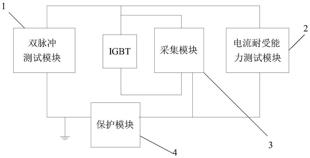
[0034] An embodiment of the present invention provides an IGBT device test circuit, which is applied to occasions that require the IGBT to be turned on, turned off, and current withstand capability, such as figure 1 As shown, it includes: a double pulse test module 1 , a current withstand capability test module 2 , an acquisition module 3 and a protection module 4 .

[0035] In the dual-pulse test module 1 of the embodiment of the present invention, its first terminal is connected to the IGBT collector, and its second terminal is respectively connected to the first terminal and the ground terminal of the protection module for testing the turn-on and turn-off performance of the IGBT.

[0036] Usually, the understanding of IGBT is mainly through reading the corresponding data sheet. The parameters described in the data sheet are based on some given external parameter conditions. However, the external parameters in practical applications are personalized, often will be different,...

Embodiment 2

[0067] The embodiment of the present invention provides a kind of IGBT device test method, tests the IGBT device based on the IGBT device test circuit of embodiment 1, such as Image 6 As shown, the IGBT device test methods include:

[0068] Step S11: closing the charging switch, and simultaneously opening the discharging switch, the first isolating switch and the second isolating switch.

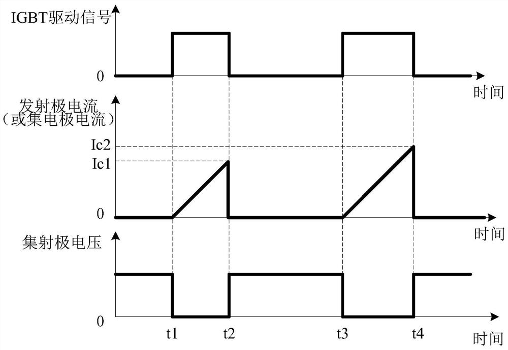
[0069] Step S12: Determine whether the capacitor voltage reaches the preset test voltage. When the capacitor voltage reaches the preset test voltage, close the second isolating switch, receive the conduction drive signal sent by the external controller, conduct a current withstand capability test on the IGBT, and close The driving signal is used to control the conduction of the IGBT.

[0070] Such as Figure 7 As shown, the current withstand capability test is performed on the IGBT, including:

[0071] Step S21: Set the square wave current amplitude according to the IGBT rated current am...


PUM


Abstract

The invention discloses an IGBT device test circuit and test method. The test circuit comprises a double-pulse test module used for testing on and off performance of an IGBT, a current endurance capability test module used for testing the current endurance capability of the IGBT under the condition of simulating the bipolar short circuit of a converter valve, an acquisition module used for acquiring the collector voltage and the emitter current of the IGBT, and a protection module used for cutting off the connection between the double-pulse test module and the IGBT when the collector voltage and/or emitter current of the IGBT exceed/exceeds a corresponding preset threshold(s). According to the invention, the switching-on and switching-off performance of the IGBT is tested by using the double-pulse test module, and the situation that the surge current impacts the IGBT under the bipolar short circuit condition of the converter valve is simulated by using the square wave current continuously output by a current source, so that the comprehensiveness and diversity of the IGBT performance test are further improved.

Description

technical field [0001] The invention relates to the technical field of power electronics, in particular to an IGBT device test circuit and a test method. Background technique [0002] In recent years, with the vigorous development of power electronics technology, the utilization efficiency and scale of renewable energy such as wind energy and solar energy have continued to expand, and the demand for renewable energy grid integration, distributed generation grid integration, and asynchronous AC grid interconnection has continued to rise. The advantages of multi-terminal voltage source converter for HVDC transmission are more prominent. The biggest problem for the multi-terminal HVDC transmission system is that due to the small inductance of the line, the line current will rise rapidly when a fault occurs, and the current in the bridge arm of the converter valve will also increase rapidly. According to the fault waveform in engineering applications, the conversion When a bipo...

Claims


Application Information

Patent Timeline
IPC IPC(8): G01R31/26G01R31/52
CPCG01R31/2608G01R31/2617G01R31/52
Inventor 李尧圣李金元杨晓亮陈中圆陈艳芳李翠刘颖含
Owner GLOBAL ENERGY INTERCONNECTION RES INST CO LTD
Why Eureka
Try Eureka