
Temperature sensor installation method for infrared radiometer in vacuum low-temperature environment

A temperature sensor, vacuum and low temperature technology, used in the field of calibration and calibration, infrared radiation measurement, can solve the problems of few calibration points, narrow calibration temperature range, inability to achieve high-precision on-orbit calibration, etc., to achieve reliable, tight and perfect temperature The effect of coupling

Inactive Publication Date: 2020-09-29
BEIJING ZHENXING METROLOGY & TEST INST
View PDF6 Cites 1 Cited by
  • Summary
  • Abstract
  • Description
  • Claims
  • Application Information

AI Technical Summary

Problems solved by technology

[0008] Traditional on-orbit radiation parameter calibration has few calibration points, generally one or two-point calibration, and the calibration temperature range is narrow, which cannot meet the current infrared load calibration and calibration requirements of on-orbit radiation parameters, and requires a new high-performance calibration source. , if the calibration source is not traceable and transferred, its value cannot be guaranteed to be accurate, and high-precision on-orbit calibration cannot be achieved. Therefore, in order to ensure the accurate traceability of the calibration source, high-precision traceability and Calibration, which requires the use of an infrared radiometer in a vacuum and low temperature environment, as a value transfer and infrared radiation value measurement device, to ensure the traceability of the value and the accuracy of the value measurement, while the external calibration source is the infrared radiometer to achieve radiation Key components for meter calibration and target infrared radiation measurement

Method used


Image

  • Temperature sensor installation method for infrared radiometer in vacuum low-temperature environment
  • Temperature sensor installation method for infrared radiometer in vacuum low-temperature environment
  • Temperature sensor installation method for infrared radiometer in vacuum low-temperature environment

Examples


Embodiment Construction

[0022] The vacuum low-temperature environment of the present invention is the environment in a liquid nitrogen refrigeration vacuum chamber, and the temperature of the inner wall of the vacuum chamber is 77K.

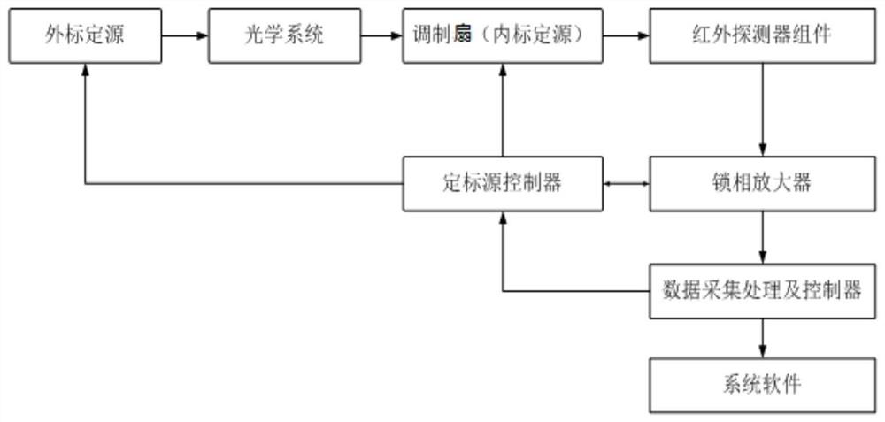
[0023] The infrared radiometer is composed of the following main components: optical system, internal calibration source, external calibration source, infrared detector assembly, lock-in amplifier, calibration source controller, data acquisition processing and controller. Such as figure 1 shown.

[0024] The internal calibration source and the external calibration source are used for calibration of the infrared radiometer, and the external calibration source is a vacuum standard blackbody; the internal calibration source is a moving vacuum standard blackbody integrated with the modulation fan;

[0025] The optical system is used to collect target light;

[0026] The modulation fan is placed between the optical system and the infrared detector assembly to modulate the ...


PUM


Abstract

The invention discloses a temperature sensor installation method for an infrared radiometer in a vacuum low-temperature environment. The method comprises the steps: enabling a temperature sensor and ametal indium powder to be placed in an installation hole of an external calibration source radiation plate at the same time, carrying out heating to enable the metal indium powder to be melted, and achieving connection of the temperature sensor and the radiation plate through solidified metal indium after the metal indium powder is cooled. In the invention, the temperature sensor and the externalcalibration source radiation plate are tightly and perfectly coupled so that the temperature control system can reliably measure and control the temperature of the external calibration source throughthe temperature sensor.

Description

technical field [0001] The invention belongs to the technical field of infrared radiation measurement, calibration and calibration, in particular to a method for installing a temperature sensor for an infrared radiometer in a vacuum and low temperature environment. Background technique [0002] At present, with the development of technology, the application of infrared imagers has been extended to near space and outer space. These systems include space infrared observation system, near space detection system, and spaceborne infrared remote sensing system. With the technical and tactical performance of these infrared load With the gradual increase in requirements, high-precision quantitative detection has become an inevitable trend for the further development of infrared loads. [0003] Radiation parameter calibration is the basis and prerequisite for quantitative detection of infrared loads. Through radiation parameter calibration, the radiation value of the target can be qu...

Claims


Application Information

Patent Timeline
IPC IPC(8): G01J5/02
CPCG01J5/0205G01J5/80
Inventor 张玉国孙红胜张鑫吴柯萱孙广尉
Owner BEIJING ZHENXING METROLOGY & TEST INST
Learn More