Laser radar detection device based on lens and integrated beam transceiver

A technology of laser radar and detection device, which is applied to measurement devices, instruments, and re-radiation of electromagnetic waves. Low, simple light path effect

Active Publication Date: 2020-09-29
SHANGHAI JIAOTONG UNIV
View PDF11 Cites 14 Cited by
  • Summary
  • Abstract
  • Description
  • Claims
  • Application Information

AI Technical Summary

Problems solved by technology

[0008] Generally speaking, the above lidars have problems such as high control complexity, limited scanning capabilities, low beam receiving efficiency, and inability to integrate transceivers on a single chip.

Method used


Image

  • Laser radar detection device based on lens and integrated beam transceiver
  • Laser radar detection device based on lens and integrated beam transceiver
  • Laser radar detection device based on lens and integrated beam transceiver

Examples


Embodiment Construction

[0035] The present invention will be further described below in conjunction with the accompanying drawings and embodiments, but the protection scope of the present invention should not be limited thereby.

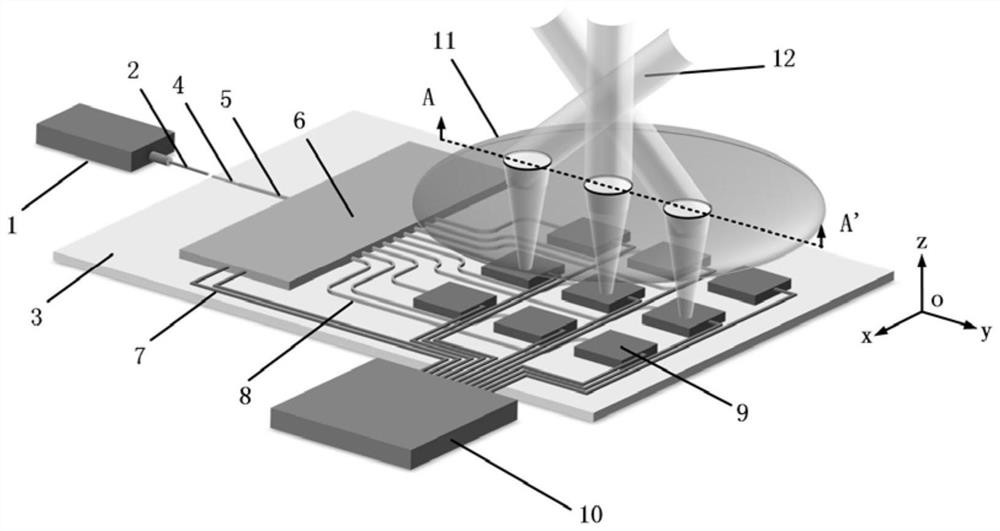
[0036] see figure 1 , figure 1 It is a schematic diagram of Embodiment 1 of the laser radar detection device based on the lens and the integrated beam transceiver of the present invention. It can be seen from the figure that the laser radar detection device based on the lens and the integrated beam transceiver of the present invention includes a laser 1, a coupling optical fiber 2, and a substrate 3. Input waveguide 4, connecting waveguide 5, 1×N optical switch 6, switch electrical interface 7, N switch output waveguides 8, N transceiver units 9, off-chip processor 10 and lens 11, N is a positive integer above 2 . The input waveguide 4, connecting waveguide 5, 1×N optical switch 6, switch electrical interface 7, N switch output waveguides 8 and N transceiver units 9 are a...


PUM


Abstract

The invention discloses a laser radar detection device based on a lens and an integrated light beam transceiver. The laser radar detection device comprises a laser, a coupling optical fiber, a substrate, an input waveguide, a connecting waveguide, a 1 * N optical switch, a switch electrical interface, N switch output waveguides, N transceiving units, an off-chip processor and a lens, wherein N isa positive integer greater than 2. According to the invention, three-dimensional detection of a target can be realized, and the device has the characteristics of two-dimensional light beam steering independent of wavelength switching, low control complexity, low electric power consumption, receiving and transmitting monolithic integration and high receiving efficiency, and is compatible with two laser ranging functions of ToF and FMCW.

Description

technical field [0001] The invention relates to a laser radar, in particular to a laser radar detection device based on a lens and an integrated beam transceiver. Background technique [0002] Lidar can be applied to the detection of the earth's geographical environment and climate monitoring. With the increase of high speed and miniaturization, it is currently playing an important role in the fields of unmanned driving and machine vision. Lidar includes two functional technologies. One is point-to-point laser ranging technology. The specific solutions currently used include Time of Fight (ToF) and Frequency-Modulated Continuous Wave (FMCW) solutions. Among them, the ToF scheme measures the distance by measuring the time delay of the transmitted and received pulsed light, while the FMCW scheme measures the distance and motion speed by beating the transmitted and received FM waves. The second is beam scanning technology, including traditional mechanical scanning and new all-...

Claims


Application Information

Patent Timeline
Patent Type & Authority Applications(China)
IPC IPC(8): G01S17/06G01S17/58G01S17/10G01S17/34G01S7/481
CPCG01S17/06G01S17/58G01S17/10G01S17/34G01S7/4817G01S7/4818Y02A90/10G01S17/894G01S7/4813G02B6/3548
Inventor 吴侃李超曹先益陈建平
Owner SHANGHAI JIAOTONG UNIV
Why Eureka
Try Eureka