
Porous meniscus substitute modeling and preparation method thereof

A modeling method and meniscus technology, applied in the field of bionic materials, can solve the problems of limited biomechanical properties, single pore structure, unfavorable implant fixation, etc., and achieve the effects of short preparation time, rapid prototyping, and avoiding stress concentration

Active Publication Date: 2020-10-02
蒋青 +4
View PDF12 Cites 10 Cited by
  • Summary
  • Abstract
  • Description
  • Claims
  • Application Information

AI Technical Summary

Problems solved by technology

[0008]Technical problem to be solved: In view of the existence of meniscus substitutes in the prior art, only for the user's appearance outline, the use of a solid structure is not conducive to implant fixation or the use of a porous structure However, there are technical problems such as single pore structure and limitations in biomechanical properties. The present invention provides a porous meniscus substitute modeling and its preparation method. The prepared porous meniscus substitute can match the user's own meniscus, which is beneficial to The penetration of joint fluid improves the meniscus substitute to transmit load, absorb vibration, and meet the needs of the knee joint. In addition, the combination of hydrogel and porous scaffold is beneficial to promote the growth of new tissue and further improve the relationship between the substitute and the surrounding tissue. binding stability

Method used

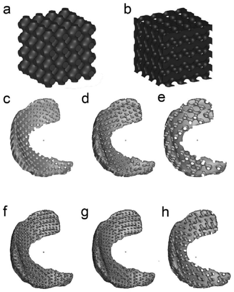

Image

  • Porous meniscus substitute modeling and preparation method thereof
  • Porous meniscus substitute modeling and preparation method thereof
  • Porous meniscus substitute modeling and preparation method thereof

Examples


Embodiment 1

[0033] A method for preparing a porous meniscus substitute model, the steps are as follows:

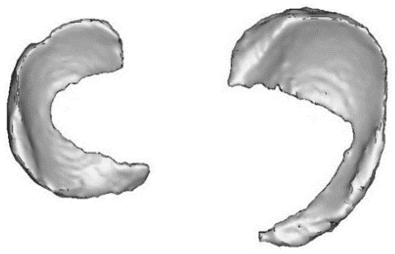
[0034] (1) Use CT to scan the meniscus of the patient, and perform image processing on the scanned image to obtain a meniscus model that matches the patient. The image processing steps are as follows: Because the distance between the meniscus and the surrounding tissue is very close, it is difficult to directly perform Contour extraction, so first binarize the image, then use the median filter to remove the noise doped in the process of CT image acquisition and digitization, and then use the edge detection method to perform edge detection and contour extraction on the filtered image. The batch-processed images are imported into Mimics software, and the curve profile is fitted to finally obtain a meniscus model that matches the patient (the 3D reconstruction model of human meniscus tissue after CT scan image processing is shown in figure 2 );

[0035] (2) Obtain the relevant peak str...

Embodiment 2

[0044] The preparation method of the porous meniscus substitute model in this example is the same as in Example 1, the difference is that the specific process of the parametric modeling method is as follows: the irregular Gyroid structure is generated by the triple periodic (TPMS) primitive parameter modeling method As a porous structure, adjust the pore shape, pore diameter and porosity of the porous meniscus substitute model by adjusting the construction parameters of the Gyroid structural surface. Gyroid surfaces see figure 1 b, The original porous structure can be generated by finding the ϕ = 0 isosurface of the TPMS equation as follows. This surface is the boundary between solid and void material phases.

[0045] (Ⅱ)

[0046] In formula (II), the pore size and surface structure are controlled by the parameters a, b and c in the above function. The porosity is controlled by the parameter d. An area of ​​Φ≥0 indicates a solid, and an area of ​​Φ<0 indicates a pore. (...

Embodiment 3

[0053] The design method of the porous meniscus substitute model in this embodiment is the same as that in Embodiment 1.

[0054] When using the prepared porous meniscus substitute model to prepare the porous meniscus substitute, the method adopted in this embodiment is the 3D printing method, using double nozzle printing, and filling the hydrogel through the 3D printer. In this embodiment, the hydrogel is poly Oxyethylene polyoxypropylene ether block copolymer, the support material is polycarbonate polyurethane (PCU) particles.

[0055] The specific steps are as follows: slice the porous meniscus substitute model to obtain the printing path of the 3D printer (the slice process is to use related software, this embodiment is Simplify 3D, set the diameter of the nozzle to 0.4 mm, the height of the printing layer to 0.3 mm, The filling rate is 20%, the printing speed is 2 mm / s, and the support filling angle is 45°. The porous meniscus substitute is sliced ​​to obtain the printing...

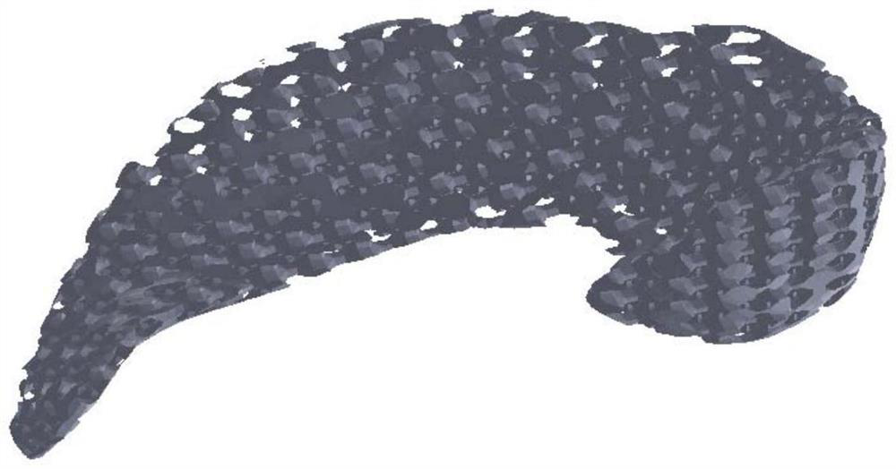

PUM

PropertyMeasurementUnit
Apertureaaaaaaaaaa
Apertureaaaaaaaaaa
Shear stressaaaaaaaaaa

Abstract

The invention provides a porous meniscus substitute modeling and a preparation method thereof. The modeling method comprises the following steps: scanning the meniscus part of a patient by using CT, performing image processing on a scanned image to obtain a meniscus model matched with the patient, performing parameter acquisition on the concentrated compression stress, shear stress and stress distribution of the femur, tibia and meniscus part of the patient at the meniscus, and setting the pore shape, pore diameter and porosity of the pores in the porous meniscus substitute by adopting a parametric modeling mode to obtain a final meniscus substitute model. The model is subjected to a 3D printing or injection molding process to obtain the porous meniscus substitute. The porous meniscus substitute prepared by the invention can be matched with the meniscus of the user, is favorable for rapid formation of meniscus tissues after transplantation, and has the biomechanical properties meetingthe requirements of knee joint parts; and in addition, through the cooperation of hydrogel and a porous scaffold, the effects of transmitting load, absorbing oscillation and improving the joint stability of the meniscus substitute can be greatly improved.

Description

technical field [0001] The invention relates to the technical field of bionic materials, in particular to a modeling method of a porous meniscus substitute and a preparation method thereof. Background technique [0002] The meniscus is a fibrocartilage structure in the knee joint, which plays an important role in cushioning and protecting cartilage. The structure of the meniscus is semi-circular, with a thicker outer periphery and a thinner inner edge; the upper surface is concave to adapt to the femoral condyle; the lower surface is flat to adapt to the tibial plateau. It is difficult to heal the meniscus after it is torn. Whether it is the tear itself, wear and tear, or partial or total surgical resection, it will lead to increased contact stress between the tibia and femur, which will significantly increase the risk of knee osteoarthritis . [0003] When the meniscus is torn in the human body, a meniscus replacement is often used. Currently used meniscus substitutes ...

Claims


Application Information

Patent Timeline
IPC IPC(8): A61F2/38
CPCA61F2/3872A61F2/30942A61F2002/30952A61F2002/30957A61F2002/30985A61F2002/30769A61F2002/30784A61F2002/3093
Inventor 朱莉娅程明孙文晨蒋青李澜
Owner 蒋青
Learn More