Sealing structure and method for refrigerating rotor compressor

A sealing structure and rotor sealing technology, applied in the field of rotor compressors, can solve the problems of inability to use rolling rotor compressors, increase the difficulty of assembly and processing, increase the frictional resistance of the end face, etc. Consistent performance and improved efficiency, reduced friction and wear

Pending Publication Date: 2020-10-02
黄石东贝压缩机有限公司
View PDF2 Cites 1 Cited by
  • Summary
  • Abstract
  • Description
  • Claims
  • Application Information

AI Technical Summary

Problems solved by technology

For example, the Chinese utility model patent (notification number: CN2528972) disclosed a cylinder assembly with a sealed piston in 2003. A sealing groove is provided on one end face of the integrated piston, and a sealing ring is placed in the sealing groove; The setting of the sealing ring improves the sealing effect between the integrated piston and the upper and lower cylinder heads, but the sealing ring is a consumable, easy to wear and damage, and often needs to be replaced, and the setting of the sealing ring increases the frictional resistance of the end face, increasing power dissipation, affecting swing efficiency
[0005] Another example is the Chinese Utility Model Patent (Notice No.: CN207145234U) which disclosed a oscillating rotor compressor with an end face seal structure in 2018. There is an end face seal groove on the seal end face, and the end face seal cover is set close to the seal end face. Including the end face seal arranged between the end face seal cover and the sealing end face; the setting of the seal improves the airtight stability, but the structure is complicated, and multiple auxiliary accessories are required, which increases the difficulty of assembly and processing
[0006] Moreover, due to the arrangement of components, the above two structures cannot be applied to rolling rotor compressors, and the scope of application is limited.

Method used


Image

  • Sealing structure and method for refrigerating rotor compressor
  • Sealing structure and method for refrigerating rotor compressor
  • Sealing structure and method for refrigerating rotor compressor

Examples


Embodiment 1

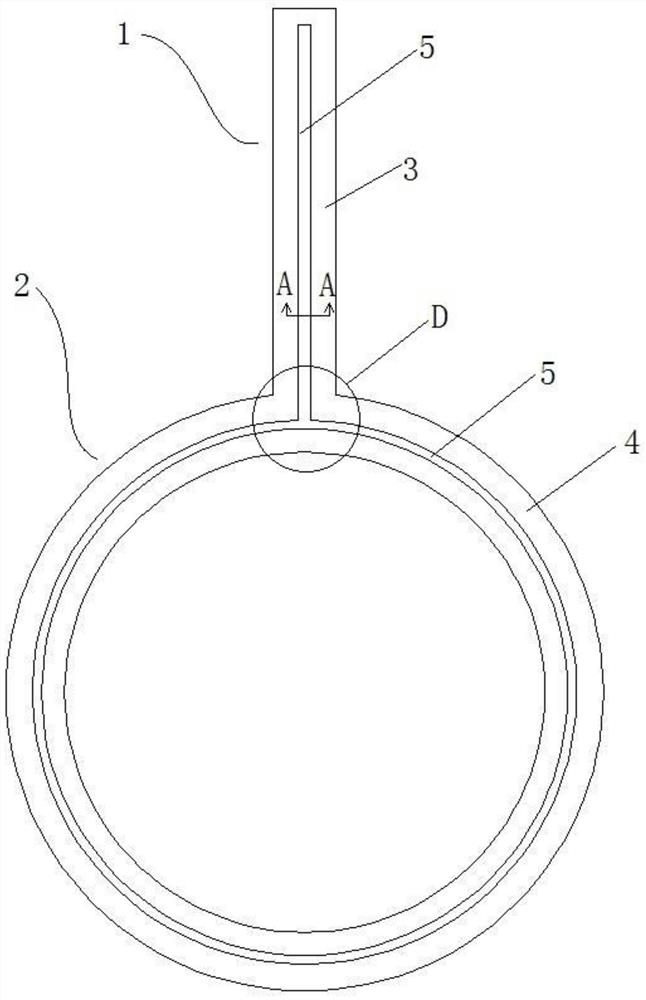
[0052] Such as figure 1 As shown, a sealing structure for a refrigeration rotary compressor, the rotary compressor has a rotor 2 and a slider 1 integrally formed; the slider 1 and the same side of the rotor 2 have sliders respectively The sealing end face 3 and the rotor sealing end face 4, the sealing structure is to set an oil groove 5 in the middle of the slider sealing end face 3 and the rotor sealing end face 4, the oil groove 5 contains the oil film, and the oil groove 5 contains a small amount Oil.

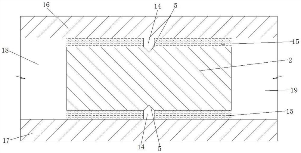
[0053] Specific design cases, such as figure 2 As shown, it is a partially enlarged schematic diagram of the oil tank 5 containing the oil film 15 in a certain state. The rotor 2 forms rotor sealing end faces between the upper end cover 16 and the lower end cover 17 of the compressor respectively. The left and right sides of the rotor 2 They are the suction cavity and the exhaust cavity respectively, and there is an air pressure difference between the suction cavity and ...

Embodiment 2

[0064] The difference between this embodiment and the first embodiment is that the shape of the oil groove is different.

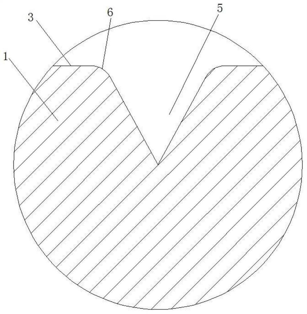
[0065] specific as Image 6 As shown, the slope of the oil groove 5 on the sealing end surface 3 of the slider near the suction end is smaller than the slope near the exhaust end.

[0066] The slopes of the two side walls of the oil groove 5 are set to be different, which can change the tendency of the oil in the oil groove 5 to form an oil film, and the slope near the suction end (i.e. the high pressure end) side is smaller, which is conducive to the formation of an oil film this time. To counteract the oil film blown away by high-pressure gas.

[0067] Such as Figure 7 As shown, it is an arc-shaped oil groove 5. The arc-shaped oil groove 5 has no sharp corners and sharp corners. During the long-term reciprocating motion, the phenomenon of stress concentration is less, which is more conducive to maintaining the structural stability of the rotor and sli...

Embodiment 3

[0069] The difference between this embodiment and the first embodiment is that an oil storage structure is provided.

[0070] specific as Figure 8 As shown, the bottom of the oil tank 5 is also provided with an oil storage structure 7; the oil storage structure 7 is a through groove corresponding to and communicating with the oil groove 5, and the through groove is circular.

[0071] The oil storage structure 7 can store more oil to continuously replenish the lost oil film, reducing the frequency of oil replenishment and prolonging the use time;

[0072] Adopting the structure of the through groove, on the one hand, it can be processed and shaped; on the other hand, it can ensure the correspondence and communication with each section of the oil groove, forming a uniform oil supply, and will not cause oil accumulation in some areas and less oil in some areas Case.


PUM


Abstract

The invention discloses a sealing structure and method for a refrigerating rotor compressor. Through formation of an oil groove in the seal face of a rotor and / or the seal face of a sliding block, theinterior of the oil groove contains a small amount of oil; the sealing structure can form small air cavities in a sealing belt between an upper cylinder head of a rotor compressor and a rotor or (and) high and low pressure cavities of the end face of a sliding block, and in a sealing belt between a lower cylinder head of the rotor compressor and the rotor or (and) the high and low pressure cavities of the end face of the sliding block; the small air cavities play a role in buffer seal in the process that high pressure gas flows toward the low pressure cavity, and meanwhile a small amount of oil can be caught for compensating oil films of high and low pressure sealing faces back and forth; the oil film play a sealing role in the clearance of the sealing face; even under the blow-away action of high-pressure end gas, the oil films can be moved at the two sides of an oil groove back and forth, and the oil film is formed on the sealing end face all the time; leakage of the high-pressure end gas to the low-pressure end is reduced, and the gas transmission volume of the compressor is ensured; and the power consumption of the compressor is reduced.

Description

technical field [0001] The invention relates to the technical field of rotor compressors, in particular to a sealing structure and sealing method for a refrigeration rotor compressor. Background technique [0002] In the refrigeration industry, the rotary compressor is a common structure widely used, which has high performance, simple structure and low cost. Especially in the air-conditioning industry, it has a high cost performance. Common structures of rotary compressors include rolling rotor type and swing rotor type; figure 1 with figure 2 As shown, it is a swing-type rotor compressor. One side of the rotor is the air inlet (low-pressure end), and the other end has an exhaust port (high-pressure end). There is a small gap between the rotor end face and the end cover, and there is an oil film in the gap , forming an oil film sealing surface. [0003] With the existing rotor sealing structure, there is a small gap between the rotor end face and the end cover. Affected...

Claims


Application Information

Patent Timeline
Patent Type & Authority Applications(China)
IPC IPC(8): F04C27/00F04C29/02
CPCF04C27/001F04C27/02F04C29/02
Inventor 杨百昌王新南陈刚戴竟雄熊勃孟碧光李华军
Owner 黄石东贝压缩机有限公司
Why Eureka
Try Eureka