
Laser scanning range finder

A laser scanning ranging and laser technology, applied in the field of laser rangefinders, can solve problems such as flag limitations, undetectable, unmeasured, etc., to improve ranging performance and user experience, expand laser radiation range, and reduce aiming The effect of precision

Pending Publication Date: 2020-10-02
LANHAI PHOTOELECTRICITY TECH CO LTD
View PDF0 Cites 0 Cited by
  • Summary
  • Abstract
  • Description
  • Claims
  • Application Information

AI Technical Summary

Problems solved by technology

[0003] Among the many application markets of laser rangefinders, the golf market is the most widely used. The measured objects are mainly flags or flagpoles. Since the size of the flag is basically fixed, once the position of the flag is far away from the observer, it can be observed through a telescope. The flag will be smaller, and in the process of measurement and use, the shaking of the user's hand or body will make it difficult for the laser rangefinder to aim at the flag, causing problems that cannot be measured or cannot be measured. Banners have significant limitations

Method used


Image

  • Laser scanning range finder
  • Laser scanning range finder
  • Laser scanning range finder

Examples


Embodiment 1

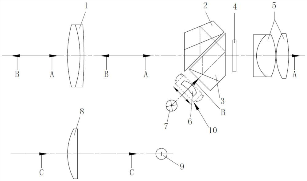
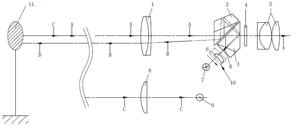
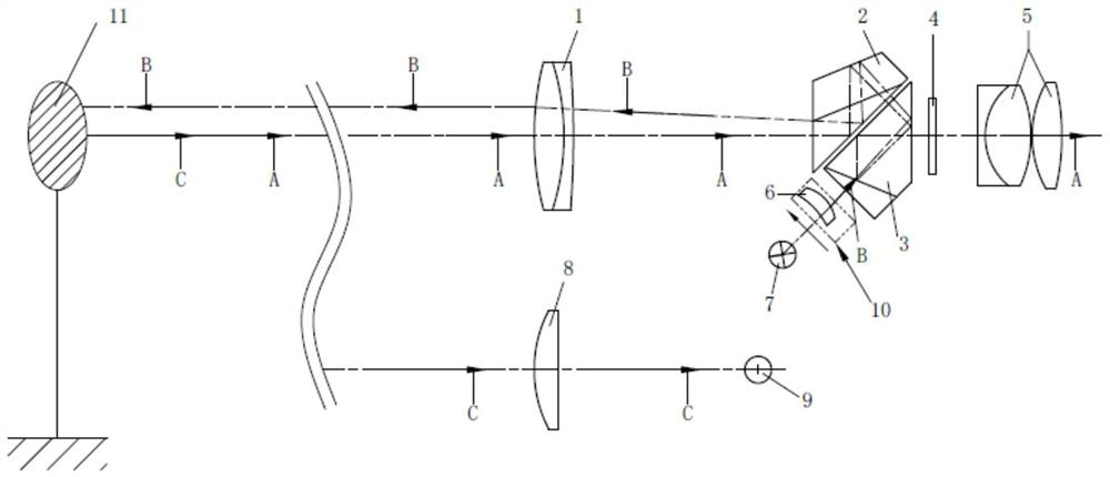
[0031] Please refer to the attached figure 1 , the present invention provides a laser scanning rangefinder, comprising: laser light emitting diode 7, emitting lens 6, prism group, objective lens 1, laser receiver 9, liquid crystal display unit 4, eyepiece 5 and drive unit 10, laser light emitting diode The laser light emitted by 7 is emitted to the measured target 11 through the transmitting lens 6, the prism group, and the objective lens 1, and the optical signal reflected by the measured target 11 is received by the laser receiver 9. According to the signal time difference between the emitted laser and the received laser, the circuit and software processing to calculate the distance information of the measured target, the distance information is displayed on the liquid crystal display unit 4 at the focal plane position of the eyepiece 5, and the distance information is received by the human eye through the eyepiece 5; the driving unit 10 drives the emitting lens 6 in the dire...

Embodiment 2

[0044] Reference attached Figure 7 , Compared with Embodiment 1, the difference between Embodiment 2 and Embodiment 1 is that the positions of the laser light-emitting diode 7, the emitting lens 6, the drive unit 10, the receiving lens 8 and the laser receiver 9 are changed, and the position of the emitting lens 6 is also added. A second emitting lens 61 is provided. The laser light emitted by the laser light-emitting diode 7 is emitted to the measured target 11 through the transmitting lens 6, and the light signal C reflected by the measured target 11 is received by the laser receiver 9 after passing through the objective lens 1, the prism group, and the receiving lens 8 in sequence. The signal time difference between emitting laser light and receiving laser light is processed by circuit and software to calculate the distance information of the measured target, and the distance information is displayed on the liquid crystal display unit 4 at the focal plane position of the e...


PUM


Abstract

The invention discloses a laser scanning range finder. The laser scanning range finder comprises a laser light-emitting diode, a transmitting lens, a prism group, an objective lens, a laser receiver,a liquid crystal display unit, an eyepiece and a driving unit, laser emitted by the laser light-emitting diode goes through the emitting lens, the prism group and the objective lens and is emitted toa measured target, an optical signal reflected by the measured target is received by the laser receiver, distance information is displayed on the display unit at the focal plane position of the ocularlens, and the distance information is received by human eyes through the ocular lens. The driving unit drives the transmitting lens to do reciprocating translation motion in the direction perpendicular to the optical axis or do back-and-forth tilting motion according to the optical axis. The laser scanning test can be realized, and the laser radiation range is expanded, so that a distant tiny target can be tested more easily, and the distance measurement capability is improved.

Description

technical field [0001] The invention belongs to the technical field of laser range finders, and more specifically relates to a laser scanning range finder. Background technique [0002] At present, the laser rangefinders including monocular telescopes on the market are basically pulsed laser rangefinders, which mainly include a monocular telescope and a laser ranging module. The telescope is used to aim at the measured object in the distance. The transmitting system in the module emits pulsed laser light, and the optical signal reflected by the measured object is received by the receiving system of the laser ranging module. The timing chip calculates the time difference between the emitted optical signal and the received optical signal, and calculates the distance of the measured object through data processing. The distance is displayed on the display unit at the focal plane position of the telescope eyepiece, and is received and read by the observer through the eyepiece. ...

Claims


Application Information

Patent Timeline
Patent Type & Authority Applications(China)
IPC IPC(8): G01S17/10G01S7/481
CPCG01S17/10G01S7/4817
Inventor 钱向伟刘崇求范益群
Owner LANHAI PHOTOELECTRICITY TECH CO LTD
Learn More