Low-power-consumption load current detection circuit applied to PWM DC-DC converter

A PWMDC-DC, load current detection technology, applied in the direction of high-efficiency power electronic conversion, AC/pulse peak measurement, output power conversion device, etc., to achieve the effect of avoiding power consumption, easy handling, and reducing loss

Active Publication Date: 2020-10-02
CHONGQING UNIV OF POSTS & TELECOMM
View PDF21 Cites 4 Cited by
  • Summary
  • Abstract
  • Description
  • Claims
  • Application Information

AI Technical Summary

Problems solved by technology

[0005] like figure 1 As shown, the traditional peak current detection circuit is also from V SW The difference is that the traditional peak current detection circuit is mostly used in the current mode control loop, and an additional compensation circuit is required. To apply the traditional peak current detection circuit to the voltage mode control loop, the problem to be solved is how to Obtain a stable current sampling signal, and facilitate subsequent processing while obtaining a stable signal during sampling

Method used


Image

  • Low-power-consumption load current detection circuit applied to PWM DC-DC converter
  • Low-power-consumption load current detection circuit applied to PWM DC-DC converter
  • Low-power-consumption load current detection circuit applied to PWM DC-DC converter

Examples


Embodiment Construction

[0020] The technical solutions in the embodiments of the present invention will be described clearly and in detail below with reference to the drawings in the embodiments of the present invention. The described embodiments are only some of the embodiments of the invention.

[0021] The technical scheme that the present invention solves the problems of the technologies described above is:

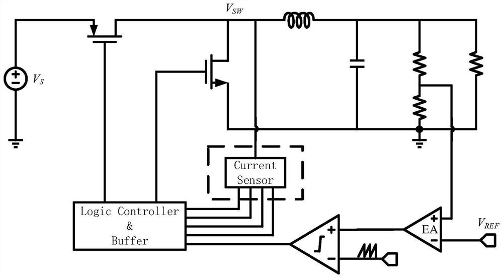
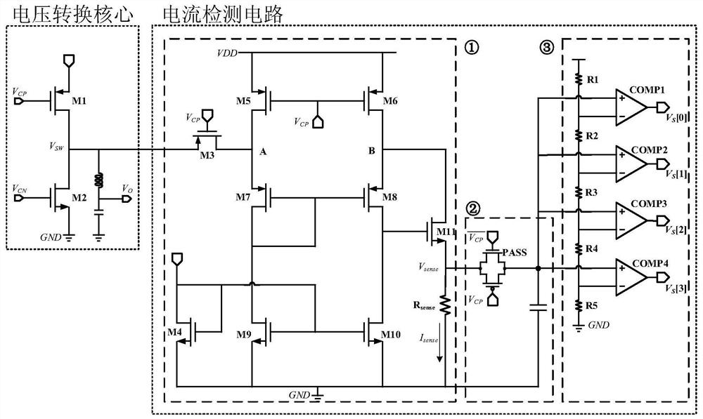
[0022] Such as figure 1As shown, it is a block diagram of the PWM Buck DC-DC system. In the figure, the power freewheeling PMOS transistor M1 and the power freewheeling NMOS transistor M2 are used as the freewheeling transistors of the Buck DC-DC, V SW The sampling signal as the peak current is received at the input end of the current detection circuit (dotted line box). The specific structure of the load current detection circuit is as follows: figure 2 As shown in the figure, it can be seen that it includes a peak current detection module ①, a sample and hold circuit ② and an analog-to...


PUM


Abstract

The invention discloses a low-power-consumption load current detection circuit applied to a PWM DC-DC converter, which belongs to the technical field of microelectronics. The circuit comprises a peakcurrent sensing module, a sampling hold circuit, an analog-to-digital conversion module and the like. A peak current detection module, a sampling hold circuit and an analog-to-digital conversion module are adopted, the input end of the peak current detection module is connected to a drain electrode of a freewheeling tube needing to be detected through a switch tube, then the output end of the peakcurrent detection module is connected with the input end of the sampling hold circuit, and the output end of the sampling hold circuit is connected with the input end of the analog-to-digital conversion circuit. The sampling hold circuit obtains a stable peak current signal through a switch capacitor, the stable peak current signal is converted into a digital signal VS [0: 3] through an analog-to-digital conversion module (3), and the change of the load current is shown through the change of the VS [0: 3] signal.

Description

technical field [0001] The invention belongs to the technical field of integrated circuit design and relates to the design of a load current detection circuit applied to PWM DC-DC. Background technique [0002] The load current detection (Load Current Detection) circuit in the DC-DC converter is often used to monitor the change of the load current. Whether it is a current control mode or a multi-modulation voltage control mode, the load current detection circuit is a basic circuit module. . In order to make the processing of the control module more convenient and stable, it is usually also hoped that the change of the load current sampled by the load current detection circuit can be converted into a digital signal. [0003] Common current detection methods for switching power converters include peak current detection (Peak Current Detection) and average current detection (Average Current Detection). Peak current detection is a detection method that reflects the magnitude o...

Claims


Application Information

Patent Timeline
Patent Type & Authority Applications(China)
IPC IPC(8): H02M3/158G01R19/04
CPCH02M3/158G01R19/04H02M1/0012H02M1/0048H02M1/0009Y02B70/10
Inventor 赵汝法周怡袁军毛鼎昌王巍
Owner CHONGQING UNIV OF POSTS & TELECOMM
Why Eureka
Try Eureka