Check patentability & draft patents in minutes with Patsnap Eureka AI!

Automatic propeller retracting device and method for unmanned aerial vehicle

An unmanned aerial vehicle and automatic technology, applied in the field of unmanned aerial vehicles, can solve the problems of increasing the weight and production cost of the unmanned aerial vehicle, and the complex structure of the unmanned aerial vehicle, and achieve the effect of reducing the occupied space.

Pending Publication Date: 2020-10-09
复亚智能科技(深圳)有限公司
View PDF0 Cites 0 Cited by
  • Summary
  • Abstract
  • Description
  • Claims
  • Application Information

AI Technical Summary

Problems solved by technology

[0003] In the prior art, the blades of UAVs are mostly folded manually, but when this method of retracting the blades is applied to the automatic hangar of UAVs, manual intervention limits the automatic use of UAVs; some unmanned The propeller is directly made into a propeller with automatic folding function, but it will inevitably increase the weight and production cost of the UAV, and will make the structure of the UAV more complicated.

Method used


Image

  • Automatic propeller retracting device and method for unmanned aerial vehicle
  • Automatic propeller retracting device and method for unmanned aerial vehicle
  • Automatic propeller retracting device and method for unmanned aerial vehicle

Examples


Embodiment 1

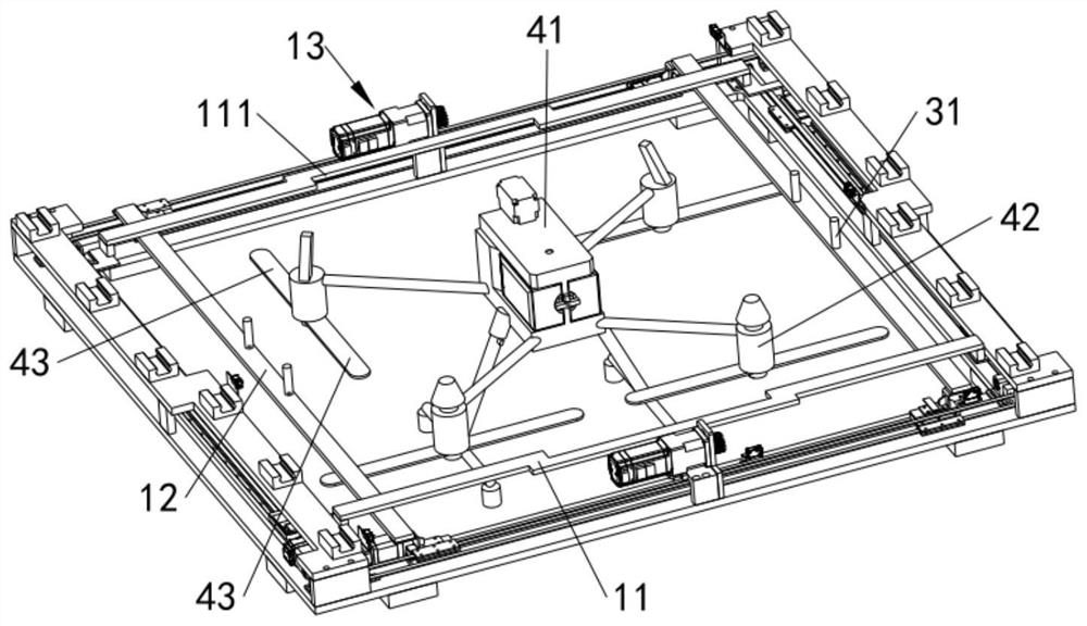
[0045] like Figure 1 to Figure 3 As shown, the UAV includes a fuselage 41 and a plurality of motors 42 distributed along the circumference of the fuselage 41 and connected to the fuselage 41 through paddle arms, and the output shaft of each motor 42 is connected with a Rotating or fixed paddles 43 . As for the structure for selectively rotating or fixing the paddle 43 relative to the output shaft of the motor 42, it is a prior art, and will not be repeated here. In order to avoid taking up a lot of space for UAV storage, the blades 43 are usually folded. The current automatic paddle retracting device has a complex structure, and the manual retraction of the paddles interferes with the automatic use of the UAV. Therefore, this embodiment provides an automatic propeller retracting device for unmanned aerial vehicles to solve the above technical problems.

[0046] The UAV automatic paddle retracting device provided in this embodiment includes a centering assembly and a paddle ...

Embodiment 2

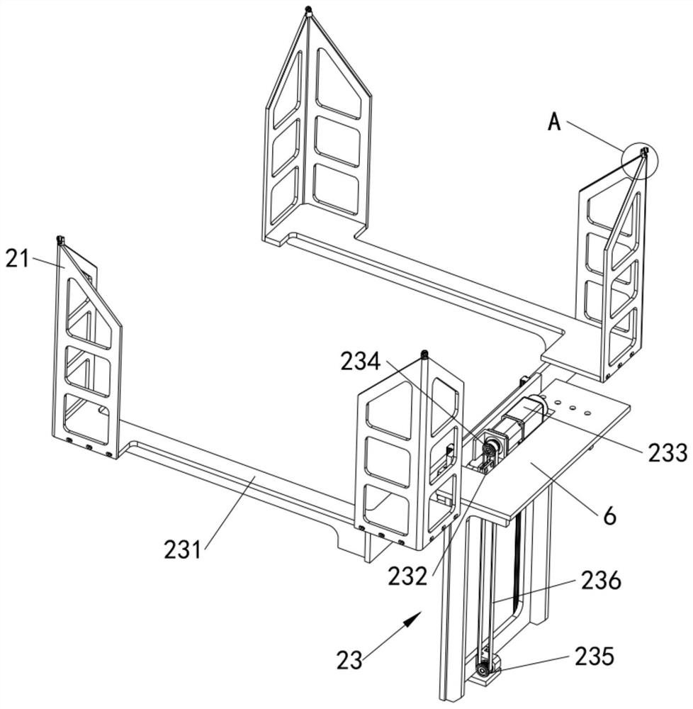
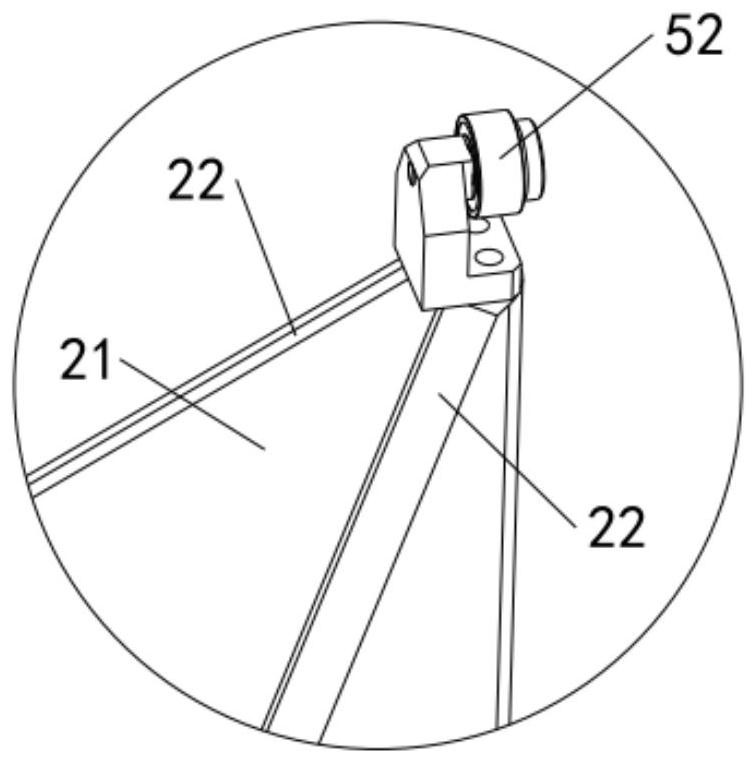
[0079] like Figure 4 and Figure 5 As shown, the difference between this embodiment and the first embodiment is that an elastic correcting component is added to replace the elastic correcting component of the first embodiment, so as to prevent the paddle 43 from stopping on the two paddle wedge surfaces 22 of the paddle sloping block 21 A problem that caused the failure to retract the propeller above the position of the sharp corner formed.

[0080] Specifically, the elastic alignment assembly includes a rotating shaft, a swing rod 51 and a torsion spring, wherein the rotating shaft is horizontally installed on the top of the paddle tilting block 21 and fixed relative to the paddle tilting block 21; the swing rod 51 is vertically arranged, and the swing rod 51 The lower end of the shaft is rotatably connected to the rotating shaft; the torsion spring connects the rotating shaft and the swing rod 51 , and the torsion spring is used to provide an external force to keep the swi...


PUM


Abstract

The invention relates to the field of unmanned aerial vehicles, and discloses an automatic propeller retracting device and method for an unmanned aerial vehicle. The automatic propeller retracting device for the unmanned aerial vehicle comprises a centering assembly capable of driving the unmanned aerial vehicle to horizontally move from a parking position to a designated position, and a paddle shifting inclined block; the top of the paddle shifting inclined block is provided with a paddle shifting wedge-shaped surface, and the paddle shifting inclined block can ascend and descend to enable the paddle shifting wedge-shaped surface to be in contact with paddles so as to push the paddles to rotate relative to the output shafts of the corresponding motors, so that each paddle is folded into an area defined by the machine body and the two adjacent motors. The centering assembly is used for driving the unmanned aerial vehicle to horizontally move to the designated position from the parkingposition; and then the paddle shifting inclined block is used for ascending and descending, so that the paddle shifting wedge-shaped surface is in contact with the paddles to push the paddles to rotate relative to the output shafts of the corresponding motors, each paddle is folded into an area defined by the machine body and the two adjacent motors, automatic folding of the paddles of the unmanned aerial vehicle is achieved, and the occupied space of the unmanned aerial vehicle is greatly reduced.

Description

technical field [0001] The invention relates to the field of unmanned aerial vehicles, in particular to an automatic propeller retracting device and a propeller retracting method for an unmanned aerial vehicle. Background technique [0002] UAVs need to take up a lot of space when they are stored, and the area occupied by the blades of the UAV is much larger than the area occupied by the fuselage of the UAV. When using the UAV automatic hangar to automatically store and charge the UAV, the volume of the UAV automatic hangar must be very large. [0003] In the prior art, the blades of UAVs are mostly folded manually, but when this method of retracting the blades is applied to the automatic hangar of UAVs, manual intervention limits the automatic use of UAVs; some unmanned The machine directly makes the blade into a blade with automatic folding function, but it will inevitably increase the weight and production cost of the UAV, and will make the structure of the UAV more comp...

Claims


Application Information

Patent Timeline
IPC IPC(8): B64C1/30B64C27/50B64C1/06B64F1/00
CPCB64C1/068B64C1/30B64C27/50B64F1/00
Inventor 曹亚兵卫大为严凯
Owner 复亚智能科技(深圳)有限公司
Features
  • R&D
  • Intellectual Property
  • Life Sciences
  • Materials
  • Tech Scout
  • Unparalleled Data Quality
  • Higher Quality Content
  • 60% Fewer Hallucinations
Learn More