Efficient winding and placing device for industrial cloth

A technology for placing devices and industrial fabrics, which is applied in the directions of winding strips, transportation and packaging, thin material processing, etc., which can solve the problems of large weight and volume of fabrics, inconvenient fabrics, and poor lamination, so as to speed up work efficiency , to ensure the effect of the degree of fit

Inactive Publication Date: 2020-10-09
泉州市晟乾工业设计有限公司
View PDF7 Cites 2 Cited by
  • Summary
  • Abstract
  • Description
  • Claims
  • Application Information

AI Technical Summary

Problems solved by technology

[0003] The structure of the cloth winding and placing device in the prior art is simple, and it is inconvenient to further guide and limit the cloth during the cloth winding process, so that the degree of bonding between the wound cloths is relatively poor, and at the same time, after the cloth is wound, , due to the large weight and volume of the fabric, it is inconvenient to remove the fabric, which affects the efficiency of the fabric's winding and placement

Method used


Image

  • Efficient winding and placing device for industrial cloth
  • Efficient winding and placing device for industrial cloth
  • Efficient winding and placing device for industrial cloth

Examples


Embodiment 1

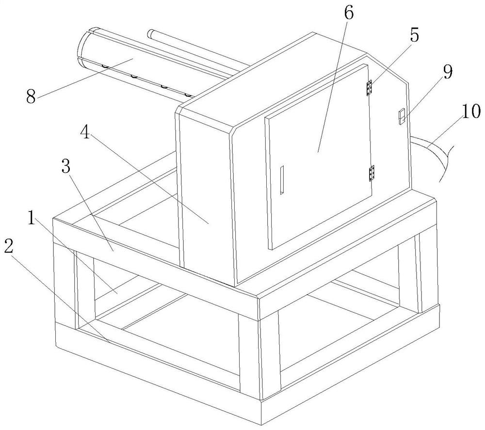
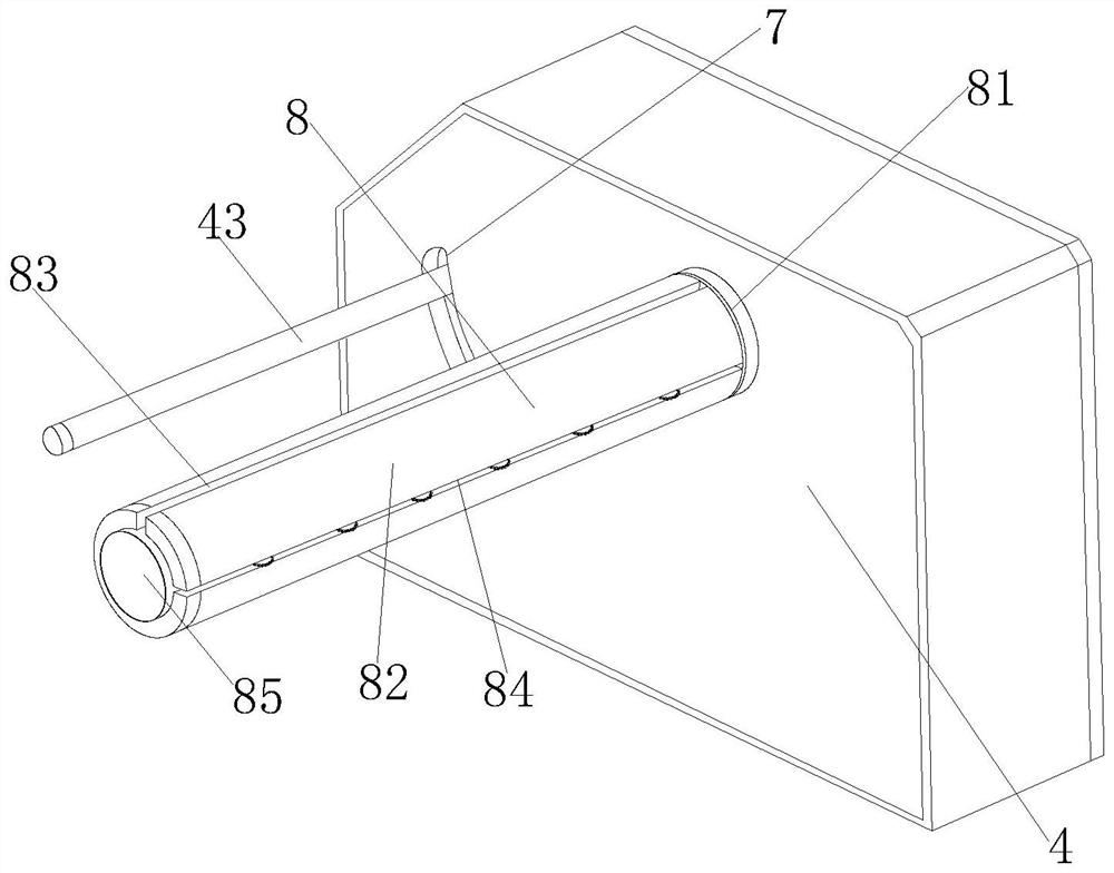
[0030] see figure 1 and figure 2 , a high-efficiency rolling and placing device for industrial cloth of the present invention, the rolling main body 1 includes a bottom frame 2, a top frame 3, a power bin 4, a hinge 5, a cover plate 6, a chute 7, a roller assembly 8, The control switch 9 and the power cord 10 are integrally formed on the top of the bottom frame 2 with a top frame 3, and the top right side of the top frame 3 is fixedly connected with a power compartment 4 by bolts, and the rear part of the right side of the power compartment 4 is connected to the cover plate 6 through a hinge 5. Hinged, a chute 7 is provided on the rear side of the left part of the power bin 4, and the roller assembly 8 is inserted into the inside of the power bin 4 to connect with it. A control switch 9 is arranged on the rear right side of the power bin 4, and a The power cord 10 and the roller assembly 8 include a connection plate 81, a cylinder holder 82, an upper slot 83, a rectangular g...

Embodiment 2

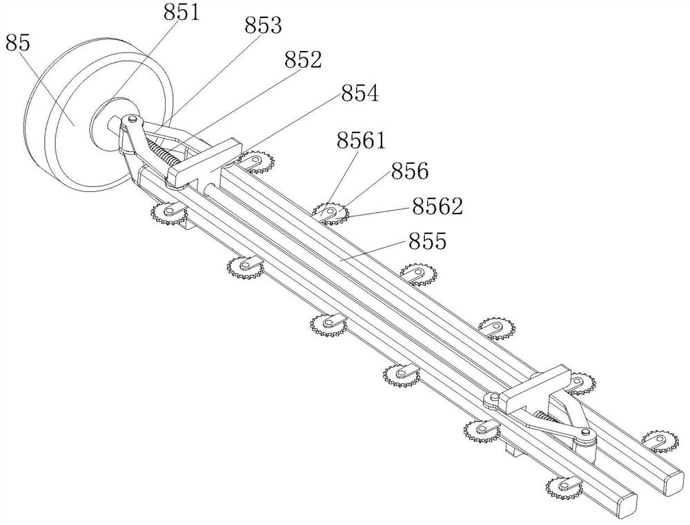
[0035] In the high-efficiency rolling and placing device for industrial cloth of the present invention, the two ends of the threaded rod 852 have threaded structures, and the threaded places on both sides of the threaded rod 852 are respectively inserted into the inner sides of two V-shaped frames 853 to be threaded with them, which is beneficial to drive The V-shaped frame is folded and unfolded, and there are two V-shaped frames 853 and clamping blocks 854, and the two V-shaped frames 853 and the clamping blocks 854 are distributed symmetrically front and back on the support bar 855, which is convenient to drive the support bar 855 to expand and support There are twelve wheels 856 in total, and six are equidistantly arranged on both sides of the support bar 855. At the same time, the support wheels 856 run through the inner side of the rectangular groove 84. Under the contact between the cloth and the support wheels 856, through the support wheels 856 Rotation facilitates the...


PUM


Abstract

The invention discloses an efficient winding and placing device for industrial cloth. A winding main body comprises a bottom frame, a top frame, a power bin, hinges, a cover plate, a sliding groove, aroller assembly, a control switch and a power line. According to the device, the power bin and the roller assembly are optimally arranged, a tension spring enables a cylindrical rod to be close to acylinder frame through a sliding frame, when cloth is wound on the cylinder frame, the cylindrical rod enables the cloth to be attached to the cylinder frame to be wound through contact with the cloth, and the fit degree of cloth winding is guaranteed; and after the cloth is wound, the inner side of the cloth is in rotating contact with groove wheels in a rectangular groove, and when the cloth ispulled, the groove wheels rotate to guide the cloth to move, the cloth is conveniently taken down, and the work efficiency of cloth winding and placing is accelerated.

Description

technical field [0001] The invention relates to the related field of cloth winding, in particular to an efficient winding and placing device for industrial cloth. Background technique [0002] Cloth is cotton, hemp and cotton-type chemical staple fibers woven by spinning, cloth, cotton cloth, and cloth. Cloth is a commonly used material in decorative materials, including chemical fiber carpets, non-woven wall coverings, linen cloth, and nylon cloth. , colored tape, flannel and other kinds of fabrics; fabrics play a considerable role in decorative display; at present, after dipping industrial fabrics, it is necessary to put industrial fabrics into winding and place them so that they can be used later For packaging and transportation, and at present, when winding industrial cloth, the cloth is usually rolled up by a winding device and then placed. [0003] The structure of the cloth winding and placing device in the prior art is simple, and it is inconvenient to further guide...

Claims


Application Information

Patent Timeline
Patent Type & Authority Applications(China)
IPC IPC(8): B65H18/26B65H19/30B65H18/10
CPCB65H18/10B65H18/26B65H19/30B65H2701/174
Inventor 邱建荣
Owner 泉州市晟乾工业设计有限公司
Why Eureka
Try Eureka