Garbage thermal cracking gasifier
A thermal cracking and gasification furnace technology, which is applied in the gasification process, the manufacture of combustible gas, and the petroleum industry. The effect of work efficiency
- Summary
- Abstract
- Description
- Claims
- Application Information
AI Technical Summary
Problems solved by technology
Method used
Image
Examples
specific Embodiment approach 1
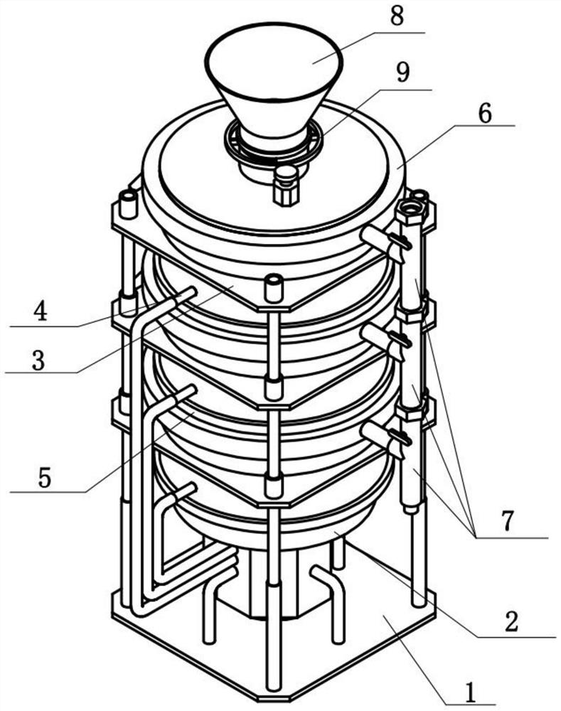
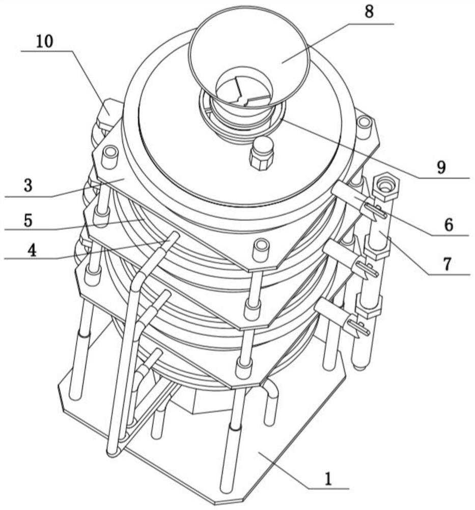
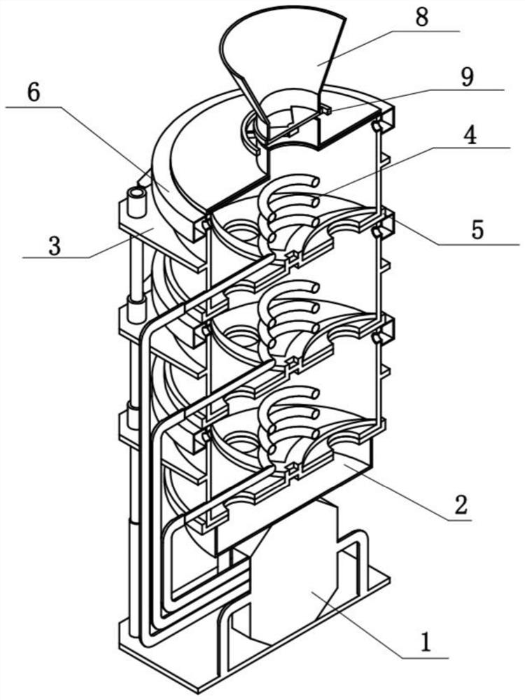
[0035] Combine below Figure 1-12 In this embodiment, a garbage thermal cracking gasifier includes a high-temperature heating component 1, an ash box 2, a reaction frame component 3, a heating component 4, a discharging component 5, an air outlet component 6, a guide component 7, and a storage component 8. The feeding assembly 9 and the driving assembly 10, the ash box 2 is detachably connected to the high temperature heating assembly 1. There are multiple high temperature heating assemblies 1, and the multiple high temperature heating assemblies 1 are detachably connected up and down in turn, the lowest high temperature The heating assembly 1 is fixedly connected to the high-temperature heating assembly 1. The middle part of the plurality of reaction outer frame assemblies 3 is provided with a heating assembly 4, and the lower ends of the plurality of reaction outer frame assemblies 3 are all rotatably connected with the discharging assembly 5, The upper end of the frame assem...
specific Embodiment approach 2
[0038] Combine below Figure 1-12 To illustrate this embodiment, the high-temperature heating assembly 1 includes a high-temperature bottom plate 1-1, a quick-installation column 1-2, a high-temperature heater 1-3, and a graded heat conduction tube 1-4. The four corners of the high-temperature bottom plate 1-1 are The quick-installation column 1-2 is fixedly connected, the high-temperature heater 1-3 is fixedly connected to the high-temperature bottom plate 1-1, and multiple graded heat conduction tubes 1-4 are fixedly connected to the front side of the high-temperature heater 1-3; high-temperature heating The device 1-3 can provide different temperatures for multiple grading heat pipes 1-4, the temperature of the highest grading heat pipe 1-4 is 200-600 degrees Celsius, and the temperature of the grading heat pipe 1-4 in the middle is 600-1200 degrees Celsius. The temperature of the lowest graded heat pipe 1-4 is 600-800 degrees Celsius, which provides different temperatures f...
specific Embodiment approach 3
[0040] Combine below Figure 1-12 To illustrate this embodiment, the reaction outer frame assembly 3 includes a reaction outer frame plate 3-1, a quick installation inserting column 3-2, a quick installation positioning column 3-3, a reaction barrel 3-4, and a gas outflow hole 3-5 , High temperature mounting holes 3-6, reaction bottom plate 3-7 and feeding holes 3-8, the four corners of the lower end of the reaction outer frame plate 3-1 are all connected with quick installation inserting columns 3-2, reaction outer frame The four corners of the upper end of the plate 3-1 are all fixedly connected with quick assembly positioning posts 3-3, the reaction barrel 3-4 is fixedly connected to the reaction outer frame plate 3-1, and the upper end of the reaction barrel 3-4 is provided with multiple The gas outflow holes 3-5, the lower part of the reaction barrel 3-4 is provided with a high-temperature installation hole 3-6, the reaction bottom plate 3-7 is fixedly connected to the low...
PUM
 Abstract
Description
Claims
Application Information
 - R&D
- Intellectual Property
- Life Sciences
- Materials
- Tech Scout
- Unparalleled Data Quality
- Higher Quality Content
- 60% Fewer Hallucinations
Browse by: Latest US Patents, China's latest patents, Technical Efficacy Thesaurus, Application Domain, Technology Topic, Popular Technical Reports.
© 2025 PatSnap. All rights reserved.Legal|Privacy policy|Modern Slavery Act Transparency Statement|Sitemap|About US| Contact US: help@patsnap.com


