Dynamic high-resolution optical wavefront phase measuring device and measuring method

A wavefront phase and measuring device technology, applied in the optical field, can solve the problems of low resolution and low precision

Active Publication Date: 2020-10-09
XI'AN INST OF OPTICS & FINE MECHANICS - CHINESE ACAD OF SCI
View PDF12 Cites 7 Cited by
  • Summary
  • Abstract
  • Description
  • Claims
  • Application Information

AI Technical Summary

Problems solved by technology

[0007] In order to solve the technical problems of low precision and low resolution of existing dynamic optical wavefront phase measurement devices, the present invention proposes a dynamic high-resolution optical wavefront phase measurement device and measurement method, which can realize the The dynamic high-resolution measurement of the surface shape of the optical element and the wave aberration of the optical system is not affected by the external environment (air flow disturbance, vibration, etc.), and the test accuracy is well guaranteed

Method used


Image

  • Dynamic high-resolution optical wavefront phase measuring device and measuring method
  • Dynamic high-resolution optical wavefront phase measuring device and measuring method
  • Dynamic high-resolution optical wavefront phase measuring device and measuring method

Examples


Embodiment Construction

[0099] The present invention will be further described below in conjunction with accompanying drawing.

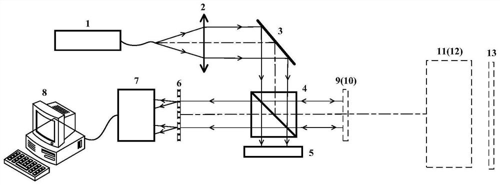
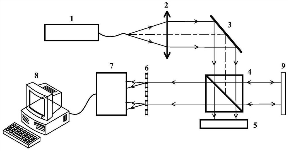
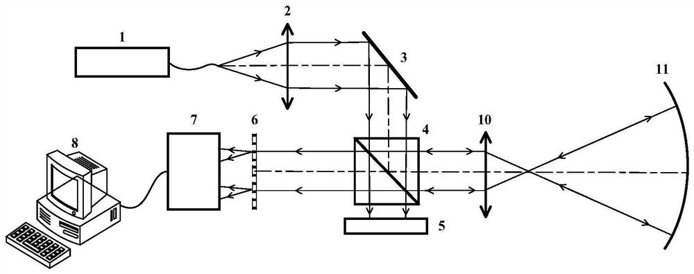
[0100] Such as figure 1 As shown, the dynamic high-resolution optical wavefront phase measurement device of the present invention consists of a laser 1, a collimating mirror 2, a plane mirror 3, a beam splitter 4, an absorber 5, a hybrid modulation grating 6, a detector 7, a computer 8, The calibration mirror 9, the standard lens 10 and the auxiliary standard flat mirror 13 are composed. figure 1 The dotted lines in the center are replaceable devices.

[0101] Laser 1, collimator 2, and plane reflector 3 are arranged sequentially along the same optical path; plane reflector 3 is used to deflect the output beam of collimator 2 onto beam splitter 4 to reduce the volume of the measuring device; beam splitter 4 is arranged on the output light path of the plane reflector 3; the beam splitter 4 transmits the output light beam of the plane reflector 3 and an absorber 5 is arrang...


PUM


Abstract

The objective of the invention is to solve the technical problems of low precision and low resolution of an existing dynamic optical wavefront phase measurement device. The invention provides a dynamic high-resolution optical wavefront phase measuring device and a measuring method, and the device and the method can achieve the active optical testing of the surface shape of an optical element and the wave aberration of an optical system through a laser, a collimating mirror, a plane mirror, a spectroscope, an absorber, a mixed modulation grating, a detector, a computer, different F # standard lenses, and a calibration mirror. The resolution is determined by the size of a detector pixel, high-resolution optical wavefront phase measurement can be achieved, and the resolution can be smaller than 0.01 mm. According to the method, a system background error is used as system data after being calibrated once, and the measured surface topography information can be calculated only by collectingan image once during actual surface shape measurement, so that compared with the traditional phase shift interference method, the method is not influenced by environments.

Description

technical field [0001] The invention belongs to the field of optics, and relates to an optical wavefront phase measuring device and method, in particular to a device and a measuring method capable of dynamically and high-resolution measuring the surface shape of an optical element and the wave aberration of an optical system. Background technique [0002] With the development of my country's space science and technology and high-power laser processing and manufacturing industry, the demand for various high-precision optical components and systems is increasing, and the requirements for the measurement accuracy of optical component surface shape and optical system wave aberration are getting higher and higher. . [0003] The static phase-shifting interferometer driven by traditional piezoelectric ceramics, because the measured wavefront phase result is obtained by phase shifting in the time domain, is easily affected by air flow disturbance and vibration, and cannot meet the d...

Claims


Application Information

Patent Timeline
Patent Type & Authority Applications(China)
IPC IPC(8): G01J9/02G01B11/24G01M11/02
CPCG01J9/02G01B11/2441G01M11/0271G01J2009/002
Inventor 段亚轩达争尚李红光李铭王璞陈晓义陈永权袁索超蔺辉
Owner XI'AN INST OF OPTICS & FINE MECHANICS - CHINESE ACAD OF SCI
Why Eureka
Try Eureka