Polaroid image measuring instrument and detection method

A technology for image measuring instruments and polarizers, applied in measuring devices, instruments, optics, etc., can solve the problems of repeated taking and placing of polarizers, inconvenience for operators to detect, etc., to improve detection efficiency, wide application range, and ensure docking accuracy Effect

Active Publication Date: 2020-10-09
江苏翔腾新材料股份有限公司
View PDF3 Cites 0 Cited by
  • Summary
  • Abstract
  • Description
  • Claims
  • Application Information

AI Technical Summary

Problems solved by technology

[0004] The above-mentioned existing technical solutions have the following defects: during the detection process, the operator puts the polarizer to be tested on the glass table, moves the digital camera to aim at the polarizer to obtain image information, and obtains the relevant dimensions after calculation by software. Then remove the polarizer; when the number of polarizers to be detected is large, the operator needs to repeatedly pick and place the polarizer, which brings inconvenience to the operator's detection work

Method used


Image

  • Polaroid image measuring instrument and detection method
  • Polaroid image measuring instrument and detection method
  • Polaroid image measuring instrument and detection method

Examples


Embodiment 1

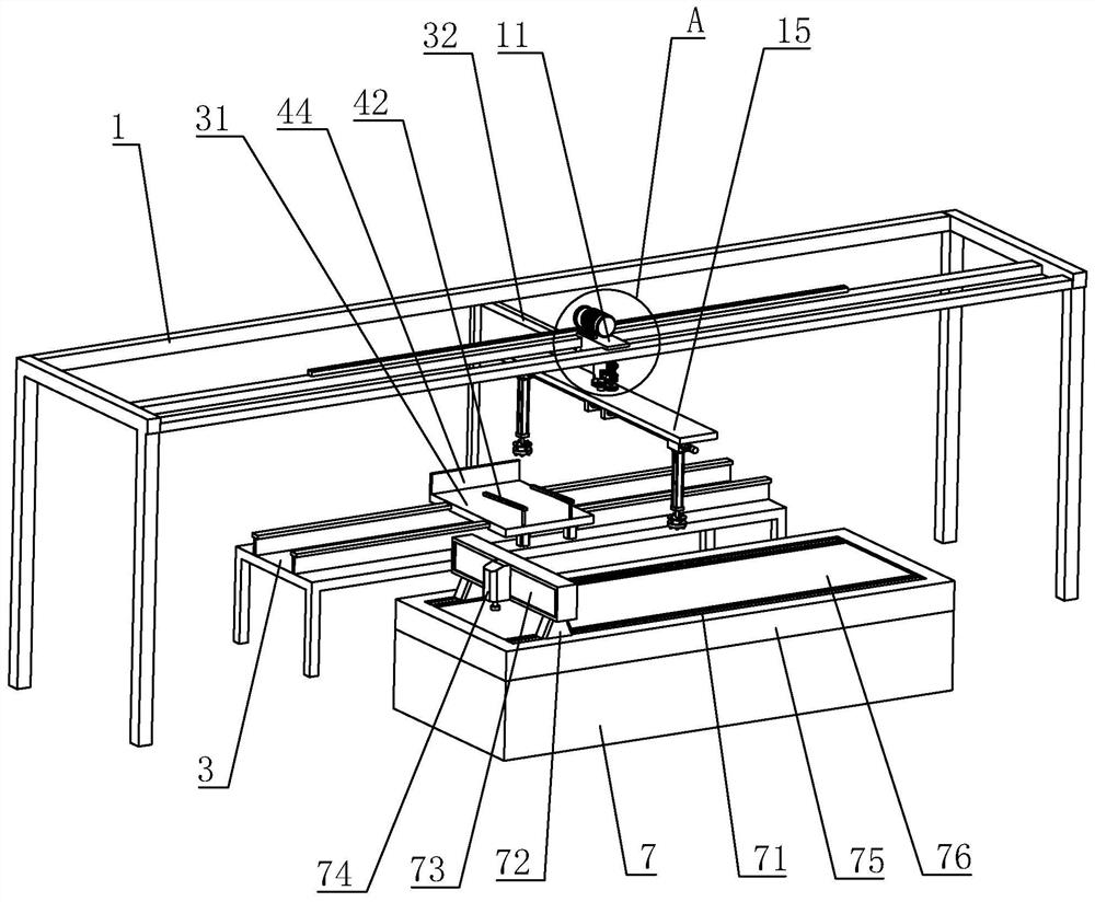
[0041] Embodiment one: if figure 1 As shown, it is a polarizer image measuring instrument disclosed in the present invention, which includes a machine 7, a frame 1 and a storage platform 3. One end of the machine 7 is connected with an X-axis track 71, and the X-axis track 71 slides with the gantry column 72. Connection, the gantry column 72 is fixedly connected with the gantry of the machine platform 7, a digital camera 74 is arranged on the horizontal sliding of the gantry of the machine platform 7, a marble platform 75 is arranged on the machine platform 7, and a glass platform 76 is fixedly connected on the marble platform 75, and the glass platform 76 is fixedly connected to the gantry. Platform 76 tops are facing digital camera 74, and the tail of machine platform 7 is connected with organic platform 7 electric control cabinets, is used to control the X-axis direction movement of machine platform 7 gantry, and the bottom of machine platform 7 is provided with machine plat...

Embodiment 2

[0053] Embodiment 2: A polarizer detection method, including a polarizer image measuring instrument, A1, first turn on the power of the measuring instrument, and then turn on the power of the computer to prevent downtime, and clear the glass platform 76 during the waiting process to avoid dust Wipe the measuring platform with a cloth.

[0054] A2. Execute the InSpec software, and the measuring instrument performs self-test.

[0055] A3. Place the polarizer to be tested on the flat plate 31 in advance, and the two vacuum chucks 17 advance synchronously with the platform. During the movement, the vacuum chucks 17 hold the polarizer in turn and place them on the glass platform 76 at intervals.

[0056] A4. The inspector controls the movement of the gantry column 72 and the digital camera 74 through the control panel, so that the digital camera 74 moves directly above the polarizer to focus, acquire an image and present it on the display screen.

[0057] A5. Call out the coordina...


PUM


Abstract

The invention relates to a polaroid image measuring instrument and a detection method. The instrument is applied to the technical field of polaroid detection equipment. The instrument comprises a machine table, an X-axis track, a gantry stand column, a machine table gantry, a digital camera, a marble platform and a glass platform, and further comprises a rack and a storage platform. A sliding seatis connected to the rack in a sliding manner; a first servo motor is arranged on the sliding seat; a motor shaft of the first servo motor is connected with a gear, a toothed bar meshed with the gearis arranged on the rack, a bearing seat is arranged on the bottom face of the sliding seat, a vertical mandrel is rotatably connected into the bearing seat, the lower end of the mandrel is connected with a supporting arm, servo air cylinders are arranged at the two ends of the supporting arm, and vacuum suction cups are installed on piston rods of the two servo air cylinders. The polaroid image measuring instrument has the effect that an operator can conveniently detect a polaroid.

Description

technical field [0001] The invention relates to the technical field of polarizer detection equipment, in particular to a polarizer image measuring instrument and a detection method. Background technique [0002] The full name of polarizer is polarizer. The imaging of liquid crystal display must rely on polarized light. All liquid crystals have two front and rear polarizers attached to the liquid crystal glass to form a liquid crystal sheet with a total thickness of about 1mm. In actual processing, it is necessary to detect the size of the polarizer to ensure the imaging quality of the LCD screen. The existing detection methods are usually carried out by means of an image measuring instrument. [0003] The Chinese patent with the notification number CN209802288U discloses a gantry imager, which has a machine platform, and one end of the machine platform is connected with an X-axis track, and the X-axis track is slidingly connected to the gantry column, and the gantry column i...

Claims


Application Information

Patent Timeline
Patent Type & Authority Applications(China)
IPC IPC(8): G02F1/13G01B11/00F16M11/04
CPCG02F1/1309G01B11/00F16M11/04
Inventor 臧晓耀李杰孙玥民
Owner 江苏翔腾新材料股份有限公司
Why Eureka
Try Eureka