
Joint suspension decompression exerciser and control method thereof

A control method and motion device technology, applied in non-surgical orthopedic operations, etc., can solve problems such as limiting joint movement function, joint stiffness, imprisoning articular cartilage pressure stress, and shear stress stimulation, so as to reduce knee joint wear and promote cartilage The effect of regeneration

Inactive Publication Date: 2020-10-13
戴江华
View PDF0 Cites 2 Cited by
  • Summary
  • Abstract
  • Description
  • Claims
  • Application Information

AI Technical Summary

Problems solved by technology

[0003] However, at present, most of the decompression devices for knee joints and hip joints are fixed decompression supports, which have extremely adverse effects on the regeneration of articular cartilage and the recovery of motor function.
[0004] Through the above analysis, the existing problems and defects of the prior art are: most of the decompression appliances for knee joints and hip joints are fixed decompression braces, which not only limit the recovery of joint motion function, but also imprison the articular cartilage regeneration. Compressive stress and shear stress stimulation have extremely adverse effects on articular cartilage regeneration and recovery of motor function
[0005] The difficulty in solving the above problems and defects is: the existing joint decompression methods such as knee joints and hip joints are mostly hinged fixed decompression, which makes the joints stiff, which not only limits the joint movement, but also confines the stress stimulation of articular cartilage regeneration. That is to say, the difficulty in solving the above problems and defects lies in maintaining the normal activities of the joint while decompressing the joint.

Method used


Image

  • Joint suspension decompression exerciser and control method thereof
  • Joint suspension decompression exerciser and control method thereof

Examples


Embodiment 1

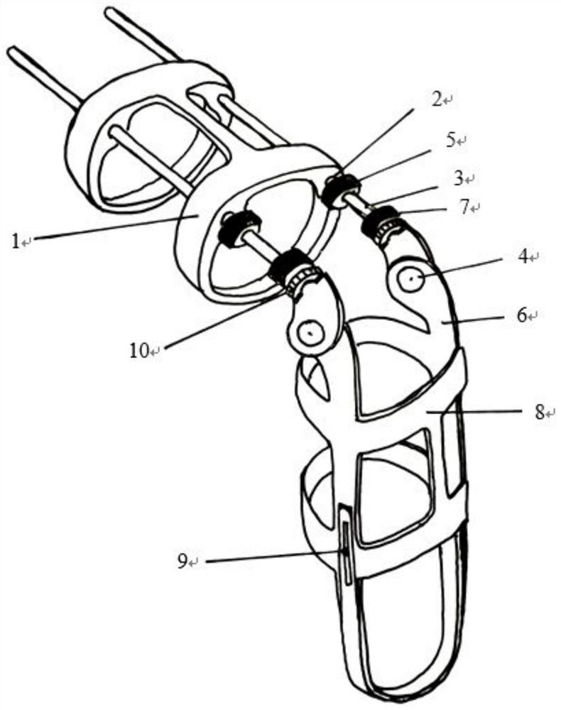
[0045] When the human body walks, the suspension support 1 is suspended above the repulsion generated by the upper permanent magnet 5 and the lower permanent magnet 7, and the left and right upper moving arms 3 (ie suspension guide arms) on the upper end of the lower leg fixing support 8 are respectively inserted into both sides of the suspension support 1 In the two pairs of parallel suspension sliding slots 2, the repulsive force of the magnetic levitation will suspend the suspension support 1 upward along the long axis of the upper moving arm 3; The knee joint is continuously decompressed, and the reaction force of the suspension when the lower limbs bear weight makes the knee joint more decompressed. In order to achieve the ideal effect of decompression of the knee joint, the suspension force can be precisely adjusted by reciprocating the suspension force adjustable knob 10 along the upper moving arm 3 so that the decompression force can achieve the desired effect.

[0046...

Embodiment 2

[0048] The present invention provides a hip joint decompression exerciser implementing the control method. The hip joint decompression exerciser adjusts the shape of the suspension bracket to a structure that matches the physiological characteristics of the body, and uses the fulcrum to support the ischial node. The joint reduces the pressure on the hip joint; the rest of the structure is the same as that of the joint suspension decompression exerciser.

[0049] In the present invention, the shape of the suspension bracket is adjusted, that is, the fulcrum of the upward suspension supports the ischial tubercle, which can reduce the pressure on the hip joint, and at the same time promote the movement function of the hip joint, and can also play a good therapeutic effect on the femoral head necrosis limb .

Embodiment 3

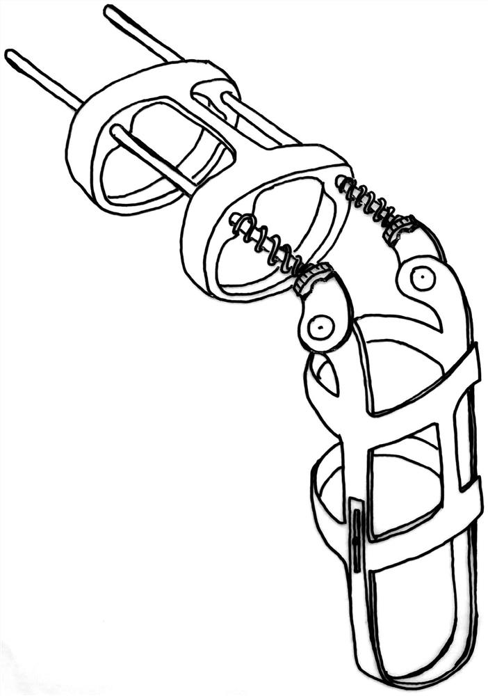
[0051] figure 2 It is a structural schematic diagram of the knee joint elastic suspension decompression exerciser provided by the embodiment of the present invention. figure 2 Only the upper permanent magnet and the lower permanent magnet are replaced with spring devices, that is, the magnetic levitation repulsion is the levitation repulsion of the spring, and the rest of the structures are the same.

[0052] It specifically includes: an upper movable arm and a lower movable arm that are movably connected by an adjustable activity chuck; the upper movable arm passes through the suspension sliding slot, and the upper movable arm is equipped with a spring device, and the elastic force of the spring device is used to make the suspension bracket upward The suspension drives the thigh and calf to separate from each other at the joint space, and the knee joint space increases;

[0053] The lower movable arm is fixed on the lower leg fixed support.


PUM


Abstract

The invention belongs to the field of medical auxiliary devices, and discloses a joint suspension decompression exerciser and a control method thereof. Left and right upper moving arms at the upper end of a joint motion supporting frame are separately inserted into two pairs of suspension sliding slots on both sides of a suspension supporting frame, and the suspension supporting frame is suspendedupwards along the long axis of the upper moving arm through the repulsion force of the magnetic suspension or the elastic repulsion force of a spring device; the suspension supporting frame upwards drives the thigh and the shank of lower limbs of a human body to be separated, so that the gap of the knee joint is increased, and the knee joint is continuously decompressed; if the action fulcrum ofthe suspension supporting frame is changed to support the ischial tuberosity, the pressure on the hip joint can be relieved. The invention can carry out full decompression on the affected knee or hipjoint and maintain the motion function of the knee or hip joint not to be influenced at the same time for patients with osteoarthritis, and provides a brand-new solution for alleviating the wear of the knee joint or the hip joint of a patient, relieving the pain of the affected limb, promoting the recovery of the motion capability of the affected knee joint, realizing virtuous cycle and finally promoting the cartilage regeneration and the perfect reconstruction of motor function.

Description

technical field [0001] The invention belongs to the field of medical auxiliary equipment, in particular to a joint suspension decompression exerciser and a control method. Background technique [0002] Currently, in osteoarthritis, the joint space is narrowed, and the cartilage is worn away, leading to adhesions, deformity and stiffness of the joints. Because the narrow joint space will aggravate the wear of the knee and hip joint surfaces, joint movement disorders will appear, and the movement disorders will lead to related muscle atrophy and atrophy, and vice versa. The two form a vicious circle, and a considerable number of patients become disabled. Joint decompression not only avoids joint wear and tear, but also provides space for the regeneration and repair of articular cartilage, which is conducive to the regeneration and rehabilitation of joint motion function. [0003] However, at present, most of the decompression devices for knee joints and hip joints are fixed d...

Claims


Application Information

Patent Timeline
IPC IPC(8): A61F5/00
CPCA61F5/00
Inventor 戴江华吴炎锋
Owner 戴江华
Learn More