Heat insulation protection device for vacuum preheating electron beam welding of pressure-resistant shell

A technology for electron beam welding and pressure-resistant shells, which is applied in the direction of electron beam welding equipment, auxiliary devices, welding equipment, etc., can solve the problems of electron beam welding machine damage, heater winding, heat radiation, etc., to solve winding, improve Heating efficiency, effect of reducing radiant heat

Active Publication Date: 2020-10-13
725TH RES INST OF CHINA SHIPBUILDING INDAL CORP
View PDF7 Cites 1 Cited by
  • Summary
  • Abstract
  • Description
  • Claims
  • Application Information

AI Technical Summary

Problems solved by technology

[0003] Based on this vacuum preheating electron beam welding method, vacuum preheating electron beam welding is required for the annular weld in the existing pressure shell components, and the required preheating temperature will reach above 600°C. The welding machine is damaged, and it is urgent to solve the problem of heat radiation to the inside of the electron beam welder under the high temperature of the pressure shell; at the same time, the pressure shell needs to be rotated during the welding process, and the connection line of the heater inside the shell will be rotated The occurrence of winding causes damage, and short circuit phenomenon is prone to occur. There is no solution for the above problems in the prior art

Method used


Image

  • Heat insulation protection device for vacuum preheating electron beam welding of pressure-resistant shell
  • Heat insulation protection device for vacuum preheating electron beam welding of pressure-resistant shell

Examples


Embodiment Construction

[0011] The present invention will be described in further detail below in conjunction with the accompanying drawings and specific embodiments.

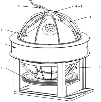
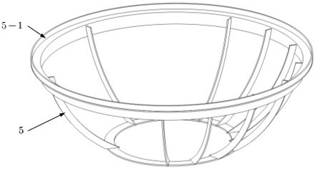
[0012] Such as Figure 1-2 As shown, a heat insulation protection device for vacuum preheating electron beam welding of pressure shells is used for heat insulation protection in vacuum preheating electron beam welding of pressure shells. The pressure shell 1 is spherical, The welding of the annular weld needs to be completed. The vacuum preheating electron beam welding device includes an electron beam welder, a turntable 3, a heating system 2 and a vacuum chamber. The pressure-resistant shell 1 is located above the turntable 3 and rotates with the turntable 3. , the heating system 2 is assembled with the pressure-resistant casing 1, and vacuum heating is performed in the vacuum chamber of the electron beam welding machine. The heating system 2 is composed of an inner heater and an outer heater, and the outer heater is supported on the...


PUM

PropertyMeasurementUnit
melting pointaaaaaaaaaa

Abstract

The invention relates to a heat insulation protection device for vacuum preheating electron beam welding of a pressure-resistant shell. The heat insulation protection device is arranged outside the pressure-resistant shell, and a framework is formed by connecting detachable stainless steel plates through bolts. The heat insulation protection device comprises an upper hemisphere heat insulation protection device body and a lower hemisphere heat insulation protection device body, wherein the upper hemisphere heat insulation protection device body is directly and fixedly connected with the uppersurface of an outer heater to form a cap-shaped structure, the lower hemisphere heat insulation protection device body is located below the outer heater, the lower hemisphere heat insulation protection device body is fixed to a rotary table to form a bowl-shaped structure, multiple layers of high-reflection metal foil are laid outside the framework for heat insulation protection, the center of theupper hemisphere heat insulation protection device body is arranged to be of a smooth cylindrical structure, and a heating circuit and a temperature thermocouple wire penetrate through the cylindrical structure. The heat insulation protection device can play a good role in heat insulation protection during vacuum preheating welding of the pressure-resistant shell, the heating efficiency is improved, and meanwhile the problem of winding in the circuit moving process is solved.

Description

technical field [0001] The invention relates to the field of metal material welding, in particular to a heat insulation protection device for vacuum preheating electron beam welding of a pressure-resistant shell. Background technique [0002] In traditional electron beam welding technology, electron beam defocus scanning is usually used for preheating, and only the surface of thin or thick plates is preheated before welding, and the preheating capacity is limited; vacuum preheating electron beam welding is a new welding method, which uses vacuum The combination of preheating and electron beam welding technology can effectively improve the weldability of special materials and improve the weld performance at the same time. [0003] Based on this vacuum preheating electron beam welding method, vacuum preheating electron beam welding is required for the annular weld in the existing pressure shell components, and the required preheating temperature will reach above 600°C. The we...

Claims


Application Information

Patent Timeline
Patent Type & Authority Applications(China)
IPC IPC(8): B23K15/00B23K15/06B23K37/00
CPCB23K15/0033B23K15/0046B23K15/06B23K37/006
Inventor 余巍高奇崔永杰张林林王东兴刘希林刘志颖
Owner 725TH RES INST OF CHINA SHIPBUILDING INDAL CORP
Why Eureka
Try Eureka