Drilling equipment for building construction

A technology for drilling equipment and building construction. It is applied in the direction of stone processing equipment, working accessories, manufacturing tools, etc. It can solve the problems of reducing drilling operation efficiency, large vibration, and inconvenient adjustment of drilling equipment, and achieves flexible operation and lifting. efficiency effect

Inactive Publication Date: 2020-10-13
曾勇
View PDF0 Cites 3 Cited by
  • Summary
  • Abstract
  • Description
  • Claims
  • Application Information

AI Technical Summary

Problems solved by technology

Now generally the staff hold the hydroelectric drill to drill the wall, and the hydroelectric drill will produce a large vibration when working, and the staff needs to push the hydroelectric drill, which increases the labor intensity of the staff; and, during actual construction Multi-directional drilling is required, and the existing drilling equipment is not easy to adjust, which reduces the efficiency of drilling operations; therefore, it is necessary to improve the existing technology

Method used


Image

  • Drilling equipment for building construction
  • Drilling equipment for building construction
  • Drilling equipment for building construction

Examples


Embodiment 1

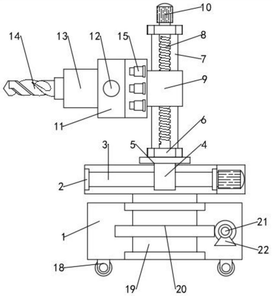
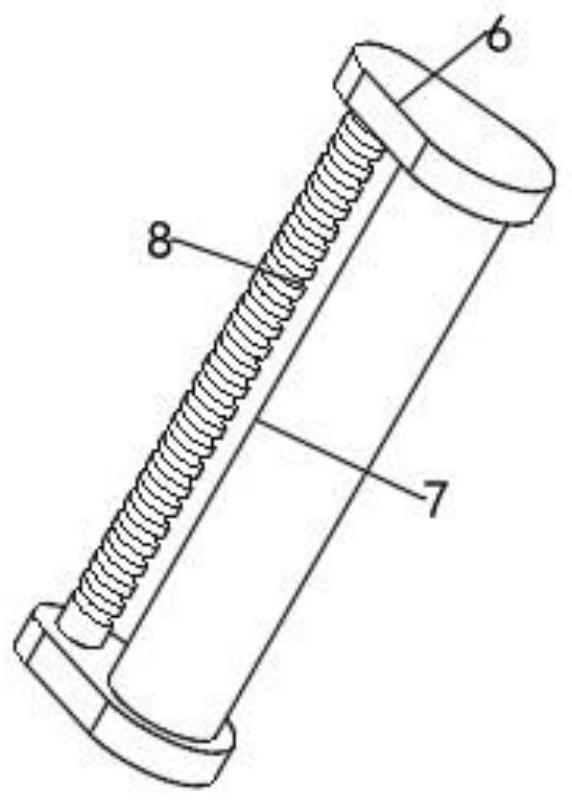
[0021] see Figure 1-5 , a kind of drilling equipment for building construction, comprising a base 1, a worktable 2 is movably assembled above the base 1, a fixed seat 5 is movably connected to the workbench 2, and a base 6 is fixedly connected to the upper end of the fixed seat 5 , the top of the base 6 is provided with another base 6, and a vertical coupling column 7 and a lifting screw 8 are fixedly connected between the two bases 6, and the coupling column 7 and the lifting screw 8 are arranged at intervals, and the lifting One end of the screw mandrel 8 extends above the base 6 of the upper end and is connected with a lifting motor 10 in transmission; a mounting seat 9 is equipped between the coupling column 7 and the lifting screw mandrel 8, and the mounting base 9 is slidably connected with the coupling column 7 and is connected with the lifting motor 10. The screw rod 8 is driven and matched; one side of the mounting seat 9 is fixedly connected with an assembly seat 11...

Embodiment 2

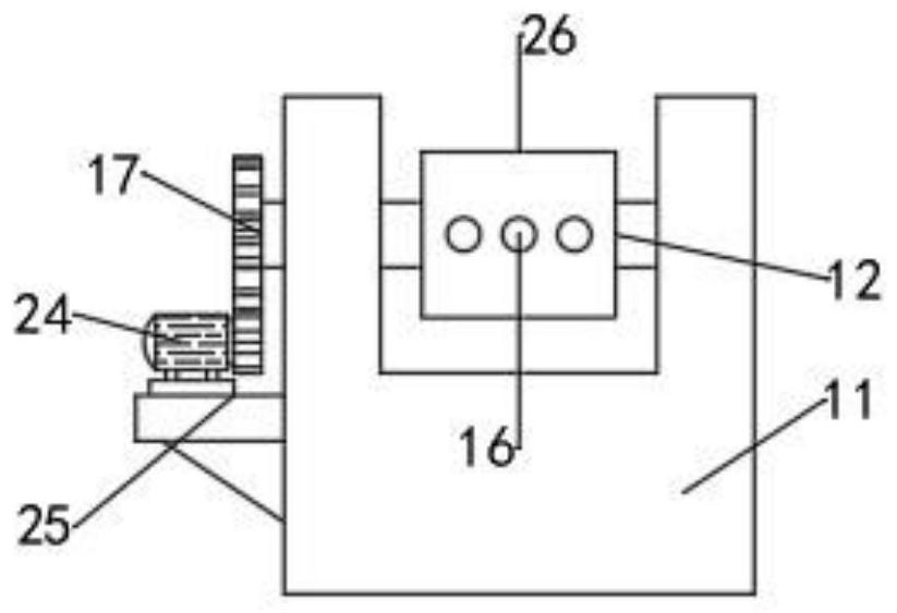
[0030] In Embodiment 1, the drilling machine 13 can carry out vertical and horizontal drilling operations under the adjustment of the turning motor 24. In actual use, multi-faceted drilling is often required in the horizontal direction. The installation angle of the hole equipment increases the labor intensity of the operator, and the manual adjustment of the installation position of the base 1 is likely to have an offset, which is not convenient for subsequent tool setting; therefore, this embodiment is improved on the basis of Embodiment 1. The improvement is: the base 1 is equipped with a vertical adjustment shaft 19, one end of the adjustment shaft 19 extends above the base 1 and is fixedly connected with the bottom surface of the workbench 2, and the adjustment shaft 19 is fixedly connected with a worm wheel 20 , the interior of the base 1 is provided with two assembly frames 22 at intervals, a worm 21 is installed between the two assembly frames 22, the worm 21 is in tran...


PUM


Abstract

The invention discloses drilling equipment for building construction. The drilling equipment comprises a base, a workbench is movably assembled above the base, and a fixed seat is movably connected onto the workbench. According to the drilling equipment for building construction, an overturning motor is arranged to control the position of an overturning seat, a drilling machine can conveniently perform multi-directional drilling operation, a plurality of limiting cylinders are uniformly distributed to be matched with limiting holes, the position of the overturning seat is conveniently and effectively fixed, the position of a cutter is prevented from changing when the drilling machine works, and drilling quality is ensured; the position of the cutter is controlled through a lifting screw rod and a sliding screw rod, tool setting is facilitated, and meanwhile, the feed amount and the feed rate of the cutter can be controlled; and in addition, the position of the workbench is controlled to rotate through meshing of a worm wheel and a worm, flexible operation of the cutter is facilitated, and drilling efficiency is improved.

Description

technical field [0001] The invention relates to the field of building construction, in particular to a drilling device for building construction. Background technique [0002] Building construction refers to the production activities in the implementation stage of engineering construction. It is the construction process of various buildings, or the process of turning the lines on the design drawings into real objects. During the construction process, it is often necessary to drill holes in the wall . Now generally the staff hold the hydroelectric drill to drill the wall, and the hydroelectric drill will generate a large vibration when working, and the staff needs to push the hydroelectric drill, which increases the labor intensity of the staff; and, during actual construction Multi-directional drilling is required, and the existing drilling equipment is inconvenient to adjust, which reduces the efficiency of drilling operations; therefore, it is necessary to improve the pri...

Claims


Application Information

Patent Timeline
Patent Type & Authority Applications(China)
IPC IPC(8): B28D1/14B28D7/00
CPCB28D1/14B28D1/146B28D7/00
Inventor 曾勇
Owner 曾勇
Why Eureka
Try Eureka