Efficiency tester for rod-pumped well system

A system efficiency, pumping unit well technology, applied in the field of pumping unit well system efficiency tester, can solve problems such as large volume, loose interface, misjudgment of system efficiency diagnosis and analysis, etc., and achieve the effect of multiple on-chip resources and fast running speed

Active Publication Date: 2020-10-13
SHENYANG KING CAREER TECH
View PDF14 Cites 2 Cited by
  • Summary
  • Abstract
  • Description
  • Claims
  • Application Information

AI Technical Summary

Problems solved by technology

At present, the dynamometer is used to test the dynamometer diagram, dynamic fluid level and electrical parameters in the oil field, and then the power meter is used to test the electrical parameters. A system efficiency tester with parameters integrated, but it cannot perform synchronous testing of dynamometer diagrams and electrical parameters
Such test data will inevitably bring misjudgment to system efficiency diagnosis and analysis
In addition, when testing electrical parameters, the voltage of the front-end three-phase motor test voltage line and the test terminal line can reach 1140V high voltage. At present, the voltage test line of the system efficiency tester in the market directly enters the operation host through the interface. If the test line is worn or exposed or the interface If the operator is not careful, it will cause casualties, which is a great safety hazard.
What's more, the communication between the system efficiency tester and the upper computer in the current market needs to install the driver. Disadvantages of heavy and inconvenient to carry and operate

Method used


Image

  • Efficiency tester for rod-pumped well system
  • Efficiency tester for rod-pumped well system
  • Efficiency tester for rod-pumped well system

Examples


Embodiment Construction

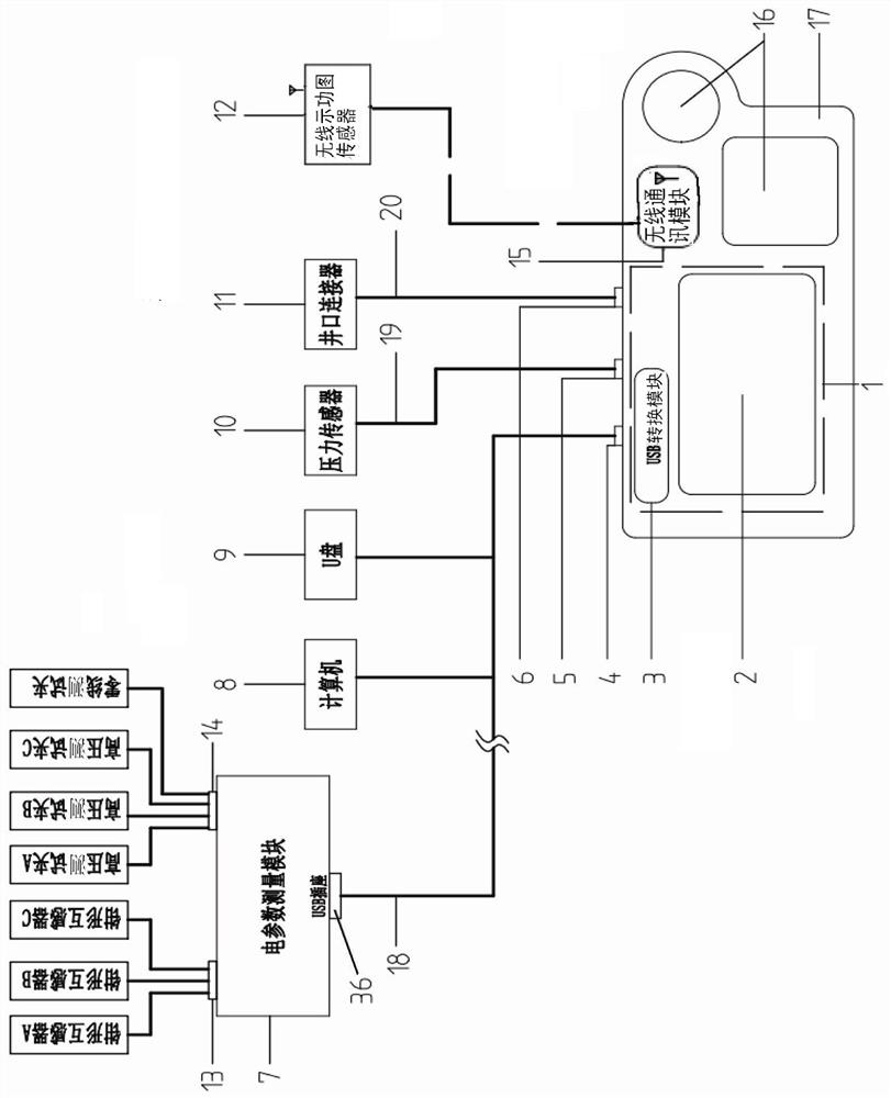
[0057] A pumping well system efficiency tester has a host 17 (hand operator).

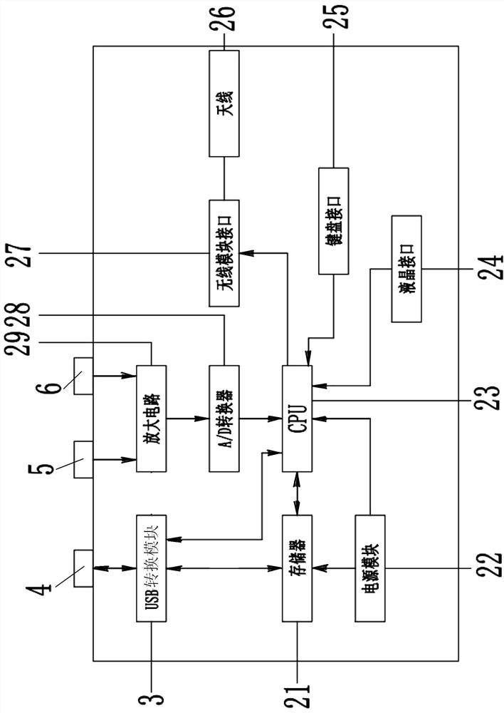
[0058] The host computer 17 has a host CPU processor 23 inside.

[0059] The pressure sensor 10 is connected to the host casing pressure test socket 5 through the host and the pressure sensor connection cable 19, and the host casing pressure test socket 5 is connected to the host amplifier circuit 29. (Pressure signal and moving liquid level signal amplifying circuit).

[0060] The wellhead connector 11 is connected to the main motor liquid level socket 6 through the host computer and the wellhead connector connecting cable 20 , and the main motor liquid level socket 6 is connected to the host amplifier circuit 29 .

[0061] The host amplifying circuit 29 is correspondingly connected with the host CPU processor 23 through the host A / D converter 28 .

[0062] The host CPU processor 23 is correspondingly connected to the host wireless communication module interface 27 (433MHZ), and the host wireles...


PUM


Abstract

The utility model discloses an efficiency tester for a rod-pumped well system. A host CPU and a wireless indicator diagram sensor are communicated through a host wireless communication module. The host USB socket is connected with the host CPU through the USB conversion module. The current transformer is connected with a filter circuit in the electrical parameter measurement module. The test clampis connected with a filter circuit in the electrical parameter measurement module through an electrical parameter internal overcurrent and overvoltage protection and step-down transformer, and then is connected with the electrical parameter CPU through an electric energy metering chip and a signal isolation circuit. The electric parameter USB socket is connected with the host USB socket and the electric parameter CPU. The electric parameter USB socket is also connected with the electric energy metering chip through an isolation power supply. The host is further connected with a pressure sensor and a wellhead connector. The host USB socket can also be connected with a computer and an external USB flash disk. The efficiency tester is a multifunctional comprehensive testing instrument for testing multiple electrical parameters, indicator diagrams, working fluid levels and the like of the oil field rod-pumped well, the system efficiency of the rod-pumped well can be calculated, and accurate data are provided for working condition diagnosis and balance analysis of the rod-pumped well.

Description

technical field [0001] The invention belongs to the field of oilfield testing equipment, and in particular relates to a pumping well system efficiency tester, which is used to test the electrical parameters of the oilfield pumping well, including voltage, current, active power, reactive power, apparent power, power factor, power Displacement curves, dynamometer diagrams, dynamic liquid levels and other multi-functional comprehensive testing instruments can calculate the efficiency of the pumping well system and provide accurate data for working condition diagnosis and balance analysis of the pumping well. Through the analysis, the best energy-saving and consumption-reducing parameter adjustment optimization scheme can be determined to ensure that the pumping well operates in the best state and improve the efficiency of the oil well system. The instrument is mainly used in the field of low-pressure testing in oil fields, and can provide accurate data for analyzing the balance a...

Claims


Application Information

Patent Timeline
Patent Type & Authority Applications(China)
IPC IPC(8): G06F1/26G06F13/42E21B47/00E21B47/04E21B47/06G01R19/00G01R22/00
CPCG06F1/26G06F13/4282E21B47/06G01R19/00G01R22/00Y02P90/02
Inventor 李光欣王国盛李小影王守志任立新李宁
Owner SHENYANG KING CAREER TECH
Why Eureka
Try Eureka