Excrement leaking plate pouring equipment for livestock breeding

A technology of manure leakage board and equipment, which is applied to supply devices, ceramic molding machines, manufacturing tools, etc., can solve problems such as the shaking of manure leakage board molds.

Inactive Publication Date: 2020-10-16
吴星佳
View PDF7 Cites 3 Cited by
  • Summary
  • Abstract
  • Description
  • Claims
  • Application Information

AI Technical Summary

Problems solved by technology

[0005] In order to overcome the shortcoming of manually shaking the mold of the leaking manure board, the technical problem to be solved by the present invention is to provide a pouring equipment for the manure board for livestock breeding that does not need manual shaking of the manure board mold

Method used


Image

  • Excrement leaking plate pouring equipment for livestock breeding
  • Excrement leaking plate pouring equipment for livestock breeding
  • Excrement leaking plate pouring equipment for livestock breeding

Examples


Embodiment 1

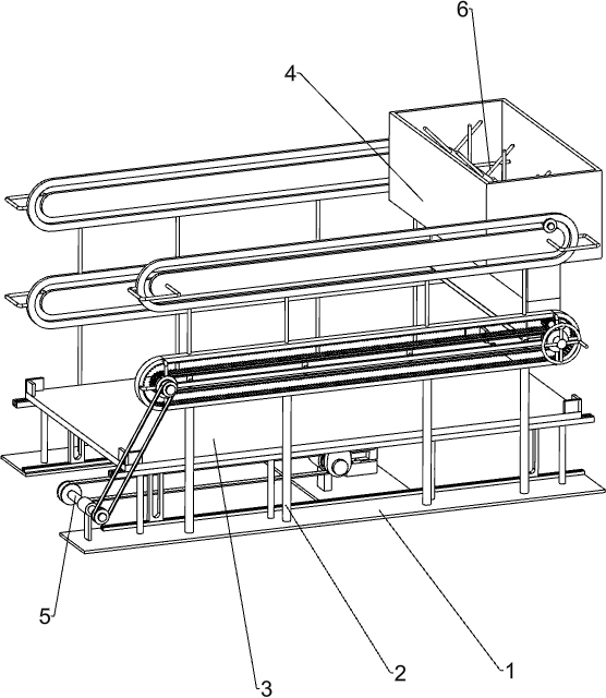
[0024] A kind of dung pouring equipment for livestock breeding, such as Figure 1-7 As shown, it includes a bottom plate 1, a mounting frame 2, a shaking mechanism 3 and a blanking mechanism 4, the front side of the top of the bottom plate 1 is connected with the mounting frame 2, and the top of the bottom plate 1 on the rear side of the mounting frame 2 is equipped with a shaking mechanism 3, and the mounting frame A blanking mechanism 4 is installed between 2 and the bottom plate 1.

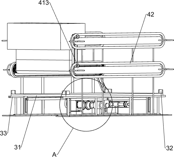
[0025] The shaking mechanism 3 includes a supporting plate 31, a block 32, a guide rail frame 33, a slotted sliding limit plate 34, a first connecting shaft 35, a long connecting rod 36, a cam 37, a second connecting shaft 38, a positioning sleeve 39, a first A bevel gear 310, a second bevel gear 311 and a servo motor 312, two rail frames 33 are connected to the top of the bottom plate 1 on the rear side of the installation frame 2, the two rail frames 33 are front and rear symmetrical, and the...

Embodiment 2

[0029] On the basis of Example 1, such as figure 1 and image 3 As shown, a linkage mechanism 5 is also included, and the linkage mechanism 5 includes a first drive belt set 51, a fourth connecting shaft 52, a fixed collar 53, a second drive belt set 54 and a fifth connecting shaft 55, and the front side rail frame The top of the bottom plate 1 on the left side of 33 is connected with a fixed collar 53, and the fixed collar 53 is connected with a fourth connecting shaft 52 in a rotational manner, and a first connecting shaft 52 is connected between the rear end of the fourth connecting shaft 52 and the front part of the second connecting shaft 38. In the transmission belt set 51, the fifth coupling shaft 55 is connected to the front end of the third coupling shaft 49 on the left side, and the second transmission belt set 54 is connected between the front end of the fifth coupling shaft 55 and the front end of the fourth coupling shaft 52.

[0030] The second connecting shaft ...

Embodiment 3

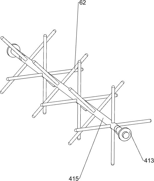
[0032] On the basis of Example 2, such as image 3 and Figure 5 As shown, a stirring mechanism 6 is also included, and the stirring mechanism 6 includes a third transmission belt set 61 and a stirrer 62, the third transmission belt set 61 is connected between the rear part of the rotating shaft 415 and the rear part of the dial shaft 412, and the rotating shaft 415 A plurality of stirring rods 62 are connected evenly spaced above.

[0033] The rotation of the dial shaft 412 can make the rotating shaft 415 rotate through the third drive belt set 61, and the rotating shaft 415 rotates to drive the stirring rod 62 to rotate, and the rotating of the stirring rod 62 can stir the cement slurry in the storage tank 416, so that the storage tank can be prevented from The cement slurry in 416 is agglomerated and agglomerated.


PUM


Abstract

The invention relates to excrement leaking plate pouring equipment, in particular to excrement leaking plate pouring equipment for livestock breeding. According to the excrement leaking plate pouringequipment for livestock breeding, an excrement leaking plate mold does not need to be shaken manually. The excrement leaking plate pouring equipment for livestock breeding comprises a bottom plate, ashaking mechanism and a discharging mechanism; one side of the upper part of the bottom plate is connected with a mounting frame; the shaking mechanism is installed on the side, close to the mountingframe, of the bottom plate; and the discharging mechanism is installed between the mounting frame and the bottom plate. According to the excrement leaking plate pouring equipment for livestock breeding, the shaking mechanism works to drive a linkage mechanism to work, the linkage mechanism can drive the discharging mechanism to work, the discharging mechanism works to discharge cement paste in thedischarging mechanism so that the cement paste can evenly fall into the excrement leaking plate mold, and the shaking mechanism can shake the excrement leaking plate mold left and right, so that theexcrement leaking plate mold does not need to be shaken manually.

Description

technical field [0001] The invention relates to pouring equipment for leaky dung slabs, in particular to pouring equipment for leaky dung slabs for animal husbandry. Background technique [0002] At present, the pouring of slabs for animal husbandry is generally done manually. The steel bars are manually put into the slab molds, and then the cement slurry is repeatedly shoveled into the slab molds with a shovel, and then the slab molds are left and right manually. Shaking, so that the cement slurry in the dung slab mold is evenly distributed, it takes a lot of time and energy, and the pouring speed of the dung slab is slow, and the workload of the workers is relatively large. [0003] Therefore urgently need to research and develop a kind of pouring equipment that does not need to manually make the dung slab mould-shaking for animal husbandry. Contents of the invention [0004] (1) Technical problems to be solved [0005] In order to overcome the shortcoming that manual ...

Claims


Application Information

Patent Timeline
Patent Type & Authority Applications(China)
IPC IPC(8): B28B1/087B28B13/02
CPCB28B1/0873B28B13/0215
Inventor 吴星佳
Owner 吴星佳
Why Eureka
Try Eureka