High-voltage cable cross interconnection loop resistance live-line detection system and method

A technology of cross-connection and loop resistance, which is applied in the measurement of resistance/reactance/impedance, short-circuit test, impedance measurement, etc. It can solve the problems of inability to detect small-sized defects in metal connections, and the inability to detect high-voltage cable cross-connection loop resistance in a timely and accurate manner. , to achieve the effect of reducing cable failure rate, strong anti-interference function, good economic and social benefits

Pending Publication Date: 2020-10-16
上海慧东电气设备有限公司
View PDF0 Cites 5 Cited by
  • Summary
  • Abstract
  • Description
  • Claims
  • Application Information

AI Technical Summary

Problems solved by technology

Currently commonly used methods include infrared temperature measurement, ultrasonic detection, and eddy current flaw detection. Infrared temperature measurement detects the surface temperature of the cable to determine whether a defect occurs. The method can only be detected when the fault is approaching. The eddy current flaw detection technology is a flaw detection method that uses the principle of electromagnetic induction to detect defects on the surface of accessories and metal connections, but it cannot detect small-sized defects inside the metal connection, such as blisters, etc.
Therefore, the existing detection methods cannot timely and accurately detect the resistance of the high-voltage cable cross-connection loop

Method used


Image

  • High-voltage cable cross interconnection loop resistance live-line detection system and method
  • High-voltage cable cross interconnection loop resistance live-line detection system and method
  • High-voltage cable cross interconnection loop resistance live-line detection system and method

Examples


Embodiment

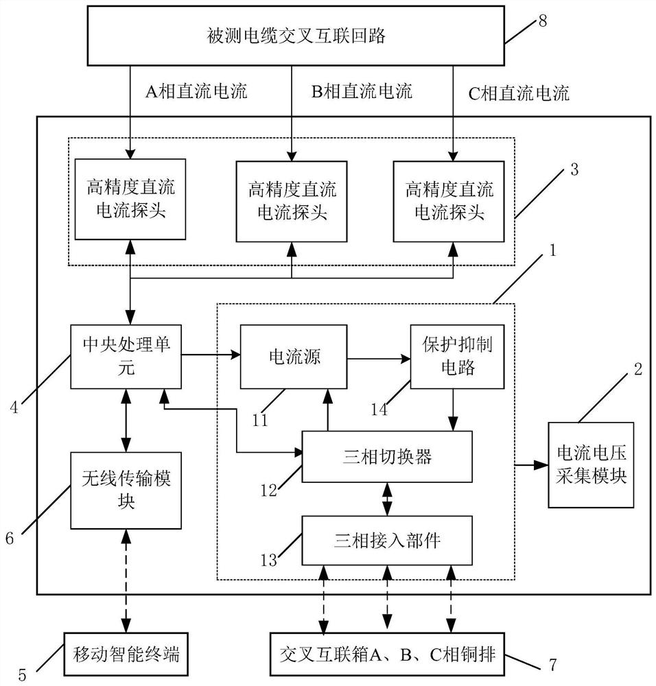
[0037] Such as figure 1 As shown, a high-voltage cable cross-connection loop resistance live detection system, the system includes:

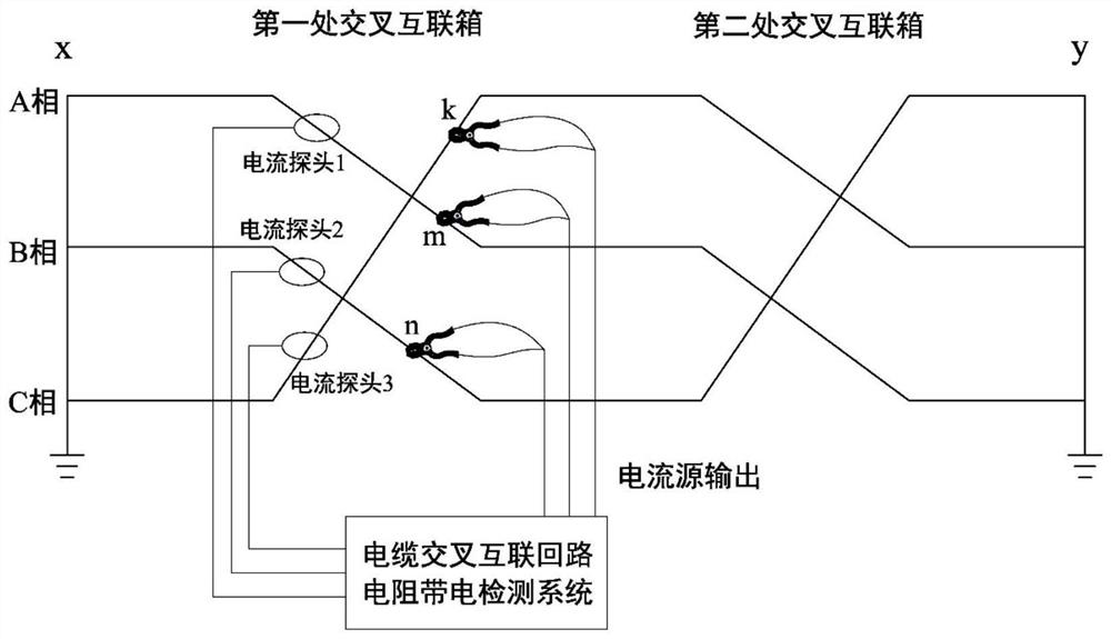
[0038] Current injection module 1: It is used to inject DC current into any two-phase metal sleeves of the A, B, and C three-phase cables of the high-voltage cable cross-connection loop on one side of the cross-connection box to form a current loop;

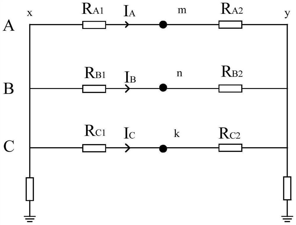
[0039] Current and voltage acquisition module 2: used to test the magnitude of the injected current and the voltage difference between the two-phase injection points forming the current loop when injecting direct current;

[0040] Loop DC current detection module 3: used to detect the magnitude of the DC current in the metal sleeves of the A, B, and C three-phase cables on the other side of the cross-connection box located on the grounding side of the high-voltage cable cross-connection loop when direct current is injected;

[0041] Central processing unit 4: used to control the switching of the t...


PUM


Abstract

The invention relates to a high-voltage cable cross interconnection loop resistance live-line detection system and method. The system comprises a current injection module which injects a direct current into any two phases of metal sleeves of a three-phase cable of a high-voltage cable cross interconnection loop at one side of a cross interconnection box to form a current loop; a current and voltage acquisition module, used for testing the magnitude of the injection current and the voltage difference between two-phase injection points forming a current loop; a loop direct current detection module, used for detecting the magnitude of direct current in a three-phase cable metal sleeve on the other side of the cross interconnection box when the direct current is injected; and a central processing unit, used for controlling the switching of the three-phase loop injected by the current injection module and calculating the loop resistance of the three-phase cable cross interconnection loop before and after the direct current injection point according to the acquired data. Compared with the prior art, the system can be used for live testing, and high-precision detection of milliohm-level resistance can be realized in a high-voltage cable cross interconnection loop with induction voltage of hundreds of volts and circulating current of dozens of amperes.

Description

technical field [0001] The invention relates to the technical field of high-voltage cable cross-interconnection loop electrification detection, in particular to a high-voltage cable cross-interconnection loop resistance electrification detection system and method. Background technique [0002] With the acceleration of urbanization in my country, the demand for power loads has increased sharply, and more and more power cables have been laid in urban overhead lines and underground power grids, and the cable lines have become longer and longer. In order to effectively reduce the sheath ring layer current, the current long cable lines adopt the high-voltage cable cross interconnection grounding system. [0003] The high-voltage cable cross-connection circuit includes: cable metal sleeve, accessory copper shell or tail pipe, intermediate joint bridge wire, ground wire, and crimping and fasteners between various parts. If any connection is bad, such as the bolt is not tight Solidi...

Claims


Application Information

Patent Timeline
Patent Type & Authority Applications(China)
IPC IPC(8): G01R27/08G01R27/18G01R31/08G01R31/52
CPCG01R27/08G01R27/18G01R31/083G01R31/088G01R31/52
Inventor 孔德武马明世张宽锋郑柒拾马俊方
Owner 上海慧东电气设备有限公司
Why Eureka
Try Eureka