
Battery replacement battery and battery replacement battery system

A technology of electric batteries and battery units, which is applied in the direction of battery/fuel cell control devices, batteries, secondary batteries, etc., which can solve problems such as difficult disassembly and transportation, large overall weight, high-intensity work and increased battery overheating accidents, and achieves easy Effect of mounting and reducing frictional resistance

Pending Publication Date: 2020-10-16
XIAMEN KING LONG UNITED AUTOMOTIVE IND CO LTD
View PDF0 Cites 3 Cited by
  • Summary
  • Abstract
  • Description
  • Claims
  • Application Information

AI Technical Summary

Problems solved by technology

[0002] Due to structural and cost constraints, most of the power batteries of new energy battery replacement buses are air-cooled to deal with the Joule heat generated by the internal resistance of the battery during charging and discharging. High-intensity work increases the probability of battery overheating accidents; and when the battery operating temperature is too low in winter, the air-cooled heat exchange form cannot quickly preheat the battery so that it can operate at an ideal operating temperature above 10°C Work
In addition, the existing replacement battery usually adopts an integrated design of the battery part and the air-cooled heat dissipation part. When changing the battery, the battery composed of the battery part and the air-cooled heat dissipation part needs to be loaded and unloaded as a whole. The overall weight is too large and it is difficult to disassemble and carry. And there is a risk of interference with other components of the bus during disassembly

Method used


Image

  • Battery replacement battery and battery replacement battery system
  • Battery replacement battery and battery replacement battery system
  • Battery replacement battery and battery replacement battery system

Examples


Embodiment Construction

[0026] Specific embodiments of the present invention will be described below with reference to the accompanying drawings.

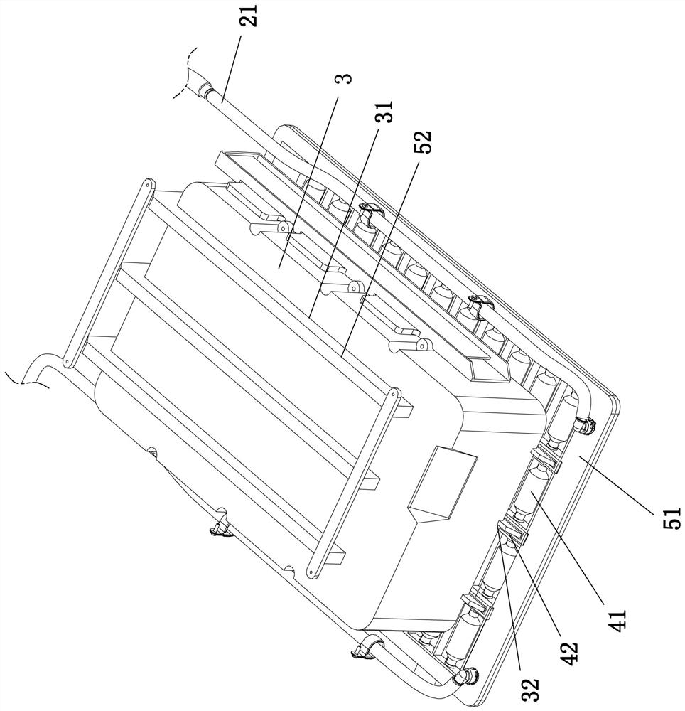
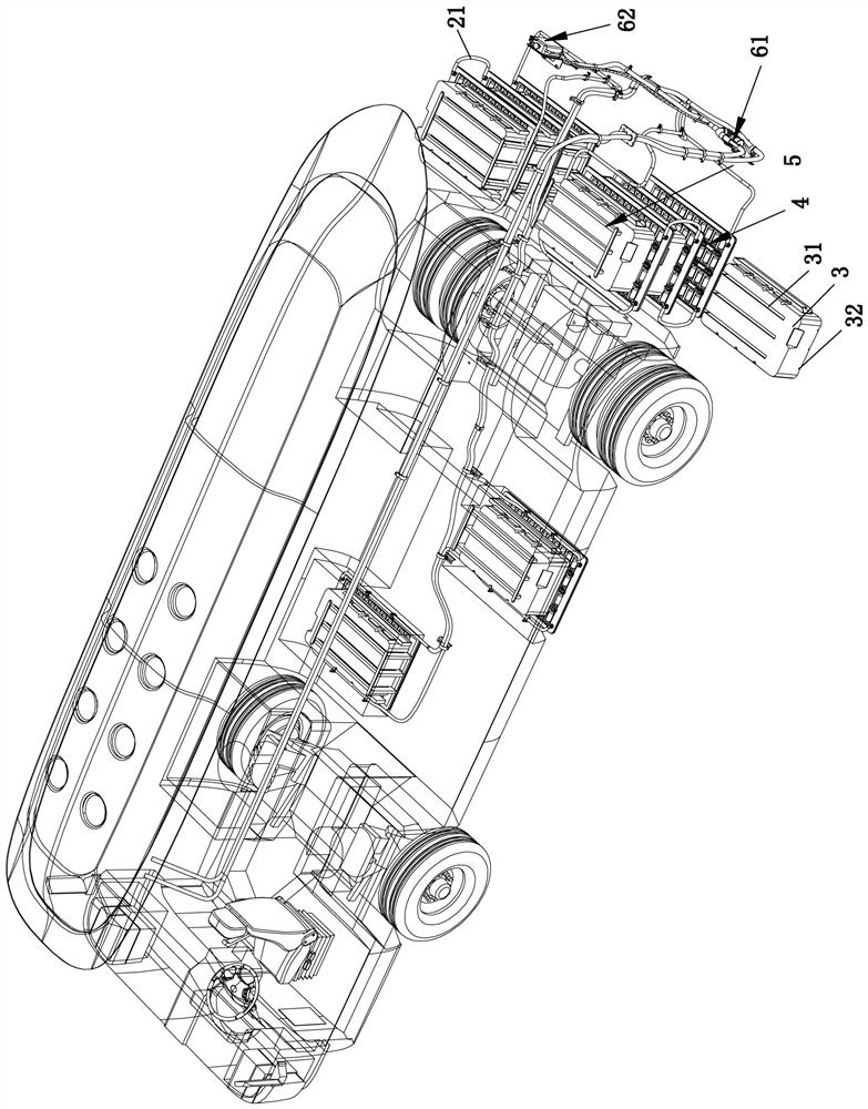
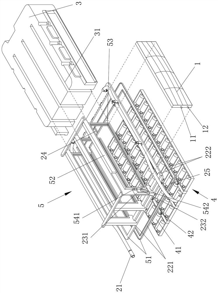
[0027] refer to figure 1 and figure 2 , a replacement battery, comprising a battery unit 3 and a heat dissipation unit, the heat dissipation unit includes a plurality of heat dissipation fins arranged at intervals, the heat dissipation unit is fixed on the vehicle body, and the battery unit 3 is provided with a plurality of heat exchange grooves 31; the battery unit 3 can be inserted It is mounted on the heat dissipation unit, and a heat dissipation fin is detachably inserted in each heat exchange slot 31 . Specifically, the groove direction of the heat exchange groove 31 is consistent with the length direction of the heat dissipation fins, so as to realize the sliding fit between the heat dissipation unit and the battery unit during the insertion and removal process.

[0028] refer to figure 1 and figure 2 , the heat dissipation unit includes a bra...


PUM


Abstract

The invention discloses a battery replacement battery and a battery replacement battery system, and relates to the technical field of battery thermal management, the battery replacement battery comprises a battery unit and a heat dissipation unit, the heat dissipation unit comprises a plurality of heat dissipation fins arranged at intervals, the heat dissipation unit is fixedly arranged on a vehicle body, and the battery unit is provided with a plurality of heat exchange grooves; the battery unit is installed on the heat dissipation unit in a pluggable mode, and a heat dissipation fin is separably inserted into each heat exchange groove. The water channels of the plurality of battery replacement batteries are connected in series through hoses to form a cooling water loop; and the cooling water loop is provided with an expansion tank, a water pump and a heat exchanger. The battery replacement battery and the battery replacement battery system have the beneficial effects that the side surfaces of the heat dissipation fins are attached to the side surfaces of the battery units, so that heat exchange is realized. The heat exchange grooves of the battery units are matched with the heatdissipation units in a plug-in mounting manner, so that the battery units are easy to disassemble and assemble.

Description

technical field [0001] The present invention relates to the technical field of battery heat management, and specifically refers to a swap battery and a swap battery system. Background technique [0002] Due to structural and cost constraints, most of the power batteries of new energy battery replacement buses are air-cooled to deal with the Joule heat generated by the internal resistance of the battery during charging and discharging. High-intensity work increases the probability of battery overheating accidents; and when the battery operating temperature is too low in winter, the air-cooled heat exchange form cannot quickly preheat the battery so that it can operate at an ideal operating temperature above 10°C Work. In addition, the existing replacement battery usually adopts an integrated design of the battery part and the air-cooled heat dissipation part. When changing the battery, the battery composed of the battery part and the air-cooled heat dissipation part needs to...

Claims


Application Information

Patent Timeline
IPC IPC(8): H01M2/10H01M10/613H01M10/615H01M10/625H01M10/6551H01M10/6567H01M10/663B60L53/80B60L58/26B60L58/27
CPCB60L53/80B60L58/26B60L58/27H01M2220/20H01M10/613H01M10/615H01M10/625H01M10/6551H01M10/6567H01M10/663Y02E60/10Y02T10/70Y02T10/7072
Inventor 苏亮王喜明李鸿海任永欢姚红贵林春敏
Owner XIAMEN KING LONG UNITED AUTOMOTIVE IND CO LTD
Learn More