Frequency stabilization and light intensity stabilization dual-piezoelectric ceramic tuning external cavity semiconductor laser
A piezoelectric ceramic and dual piezoelectric technology, applied in the field of lasers, can solve the problems of output light direction change, difficulty in realizing mode-hop-free broadband tuning, etc., and achieve the effect of compact structure
- Summary
- Abstract
- Description
- Claims
- Application Information
AI Technical Summary
Problems solved by technology
Method used
Image
Examples
Embodiment 1
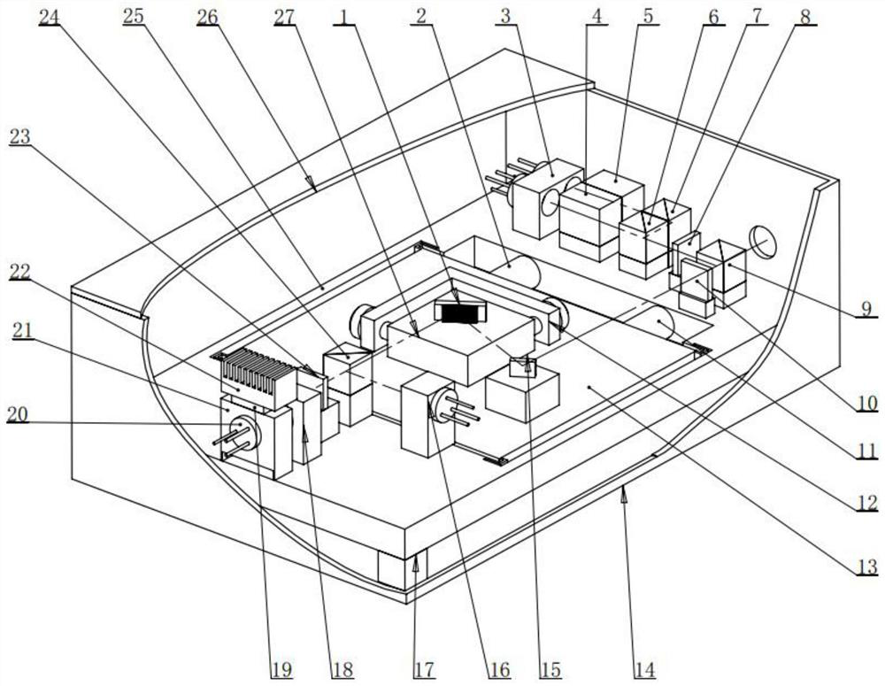
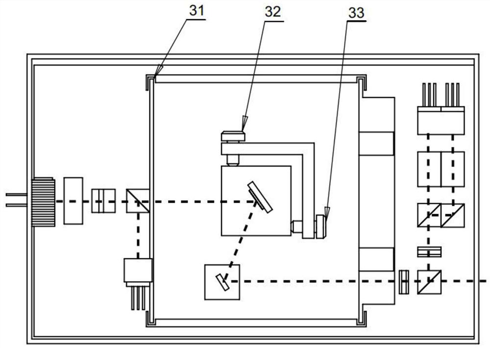
[0057] Example 1, such as figure 1 , 4 As shown, a frequency-stabilized and light-intensity dual piezoelectric ceramic tuned external cavity semiconductor laser, including:
[0058] Bottom plate 25; a cavity is provided at the center of the bottom plate 25;
[0059] blaze grating 1;
[0060] A two-dimensional adjustment module; the blazed grating 1 is fixed on the two-dimensional adjustment module, and the two-dimensional adjustment module is used to adjust the position of the blazed grating 1 in the horizontal direction;
[0061] output mirror 15;
[0062] The flexible adjustment platform 13; the two-dimensional adjustment module and the output mirror 15 are placed on the flexible adjustment platform 13; the flexible adjustment platform 13 is placed in the cavity of the bottom plate 25, and the flexible adjustment platform 13 is connected to the bottom plate 25 through a flexible connection mechanism 31;
[0063] Piezoelectric ceramic a2;
[0064] The piezoelectric ceram...
Embodiment 2
[0078] Example 2, such as figure 1 As shown, on the basis of Embodiment 1, the laser diode module includes:
[0079] laser diode 20;
[0080] Laser tube mount 21; the laser mount 21 is fixed above the bottom plate 25, and the laser diode 20 is fixed in the through hole in the laser mount 21;
[0081] A temperature compensation element 19; the laser diode 20 realizes constant temperature control through the temperature compensation element 19; the temperature compensation element 19 is installed on the surface of the laser mount 21;
[0082] Heat sink 22 ; the heat sink 22 is mounted on the temperature compensation element 19 .
[0083] In this embodiment, the laser mount 21 is fixed above the bottom plate 25 through a small contact surface to reduce heat conduction with the bottom plate 25 . The laser diode 20 realizes constant temperature control through the temperature compensation element 19 . The temperature compensating element 19 is located on the surface of the lase...
Embodiment 3
[0085] Example 3, such as figure 1 As shown, on the basis of Embodiment 1, the light intensity stabilization module includes a 1 / 2 wave plate III 23 , a polarization beam splitter PBS III 24 , and a photodetector 15 .
[0086] In this embodiment, the laser beam enters the light intensity stabilization module after passing through the collimator 18 . When in the mode of stable frequency and stable light intensity, the controller can fine-tune the current of the laser drive circuit according to the change of light intensity, so as to stabilize the light intensity. By adjusting the rotation angle of the 1 / 2 wave plate III23, the polarization plane of the laser beam can be rotated, and then the beam splitting ratio of the transmitted light and reflected light can be adjusted through the polarization beam splitter PBSIII24.
PUM
 Abstract
Description
Claims
Application Information
 - R&D
- Intellectual Property
- Life Sciences
- Materials
- Tech Scout
- Unparalleled Data Quality
- Higher Quality Content
- 60% Fewer Hallucinations
Browse by: Latest US Patents, China's latest patents, Technical Efficacy Thesaurus, Application Domain, Technology Topic, Popular Technical Reports.
© 2025 PatSnap. All rights reserved.Legal|Privacy policy|Modern Slavery Act Transparency Statement|Sitemap|About US| Contact US: help@patsnap.com


