Eureka AIR delivers breakthrough ideas for toughest innovation challenges, trusted by R&D personnel around the world.

L shaped prefabricated beam column joint

A technology of prefabricated assembly and beam-column joints, which is applied in the direction of architecture and building construction, and can solve the problems of high precision requirements for groove dimensions, weak integrity and rigidity of components, and insufficient firmness and stability of joints.

Inactive Publication Date: 2020-10-20
FUZHOU UNIV
View PDF8 Cites 3 Cited by
  • Summary
  • Abstract
  • Description
  • Claims
  • Application Information

AI Technical Summary

Problems solved by technology

However, for prefabricated structures, there are also disadvantages such as high component manufacturing cost, certain error in component size, weak component integrity and rigidity, and poor seismic effect of the structure.
[0003] CN201610303221.5 Assembled beam-column joints set through holes on the prefabricated beams, pass the connecting steel bars smaller than the diameter of the through holes through the through holes, and then pour HUPC in between, which requires higher accuracy of the reserved hole positions, and requires The size is accurate, otherwise it will not only increase the difficulty of construction, but even affect the structure. Moreover, when connecting, use the connecting steel bar to pass through the through hole on the precast column and lap the longitudinal bar on the precast beam, fix it with stirrups, and then pour concrete. , this structure uses stirrups to fix the joints, and the joints in this way are not strong enough
The connection between the prefabricated column and the prefabricated beam is provided with grooves for overlapping. This method also requires high dimensional accuracy of the grooves, and it is more troublesome to implement

Method used


Image

  • L shaped prefabricated beam column joint
  • L shaped prefabricated beam column joint
  • L shaped prefabricated beam column joint

Examples


Embodiment Construction

[0030] The terminology used herein is for the purpose of describing particular embodiments only and is not intended to be limiting of the invention. Unless otherwise defined, all terms used herein have the same meaning as commonly understood by one of ordinary skill in the art to which this invention belongs. It will be further understood that commonly used terms should be interpreted to have a meaning consistent with their meaning in the relevant art and this disclosure. This disclosure is to be considered as an example of the invention and is not intended to limit the invention to the particular embodiments.

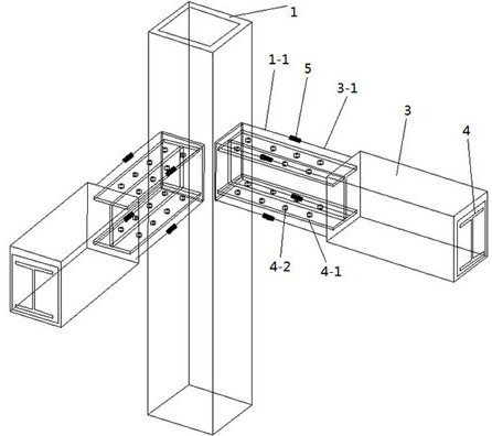
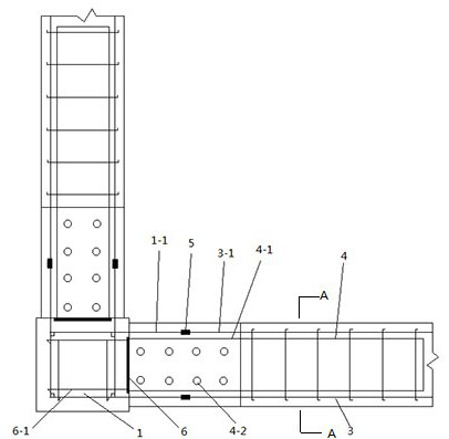
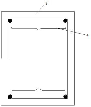
[0031] This embodiment provides an L-shaped prefabricated beam-column joint, the purpose of which is to improve the seismic performance of the structure and strengthen the strength of the structural joint. The structure includes:

[0032] A prefabricated column, including a column body 1 and a prefabricated column pouring connection part arranged on one side of the c...


PUM


Abstract

The invention belongs to the technical field of construction engineering and particularly relates to an L shaped prefabricated beam column joint which is mainly used for improving the anti-seismic property of a structure and comprises a prefabricated column and a prefabricated beam; the prefabricated column comprises a column body and a prefabricated column pouring connecting part; the prefabricated beam comprises a beam body and a prefabricated beam pouring connecting part; and the prefabricated column pouring connecting part and the prefabricated beam pouring connecting part are connected ina welding manner and are poured with concrete. Compared with the prior art, the L shaped prefabricated beam column joint is high in structural bearing capacity, large in rigidity and small in cross section, excellent in structural ductility and are more excellent in anti-seismic property. A combined structure is high in construction speed and short in construction period; before concrete pouring,profile steel forms a steel structure and has higher bearing capacity, so that a support does not need to be arranged, the construction speed is accelerated, and the construction period is shortened.

Description

technical field [0001] The invention belongs to the technical field of construction engineering, in particular to an L-shaped prefabricated beam-column joint, which is mainly used to improve the anti-seismic performance of structures. Background technique [0002] With the demand for innovation in the construction market, construction is developing in the direction of high efficiency, speed, and quality. As a new architectural form, prefabricated buildings improve construction efficiency and shorten construction time on the basis of ensuring orderly management of on-site construction. cycle, and played a very important role in the control of construction quality. However, for prefabricated structures, there are also disadvantages such as high component manufacturing cost, certain error in component size, weak component integrity and rigidity, and poor seismic effect of the structure. [0003] CN201610303221.5 Assembled beam-column joints set through holes on the prefabricat...

Claims


Application Information

Patent Timeline
Patent Type & Authority Applications(China)
IPC IPC(8): E04B1/30E04B1/58
CPCE04B1/30E04B1/185
Inventor 陈誉蒋署节乐志诚郭毅李志慧冯刚
Owner FUZHOU UNIV
Why Eureka
Eureka Blog
Learn More