
Self-locking planetary reducer

A planetary reducer and self-locking technology, which is applied to transmission parts, gear transmissions, belts/chains/gears, etc., can solve problems such as low positioning accuracy, low transmission efficiency, and complex structure

Inactive Publication Date: 2020-10-20
何金仙
View PDF4 Cites 2 Cited by
  • Summary
  • Abstract
  • Description
  • Claims
  • Application Information

AI Technical Summary

Problems solved by technology

However, these reducers still have disadvantages such as complex structure, low positioning accuracy and low transmission efficiency.

Method used


Image

  • Self-locking planetary reducer
  • Self-locking planetary reducer
  • Self-locking planetary reducer

Examples


Embodiment 1

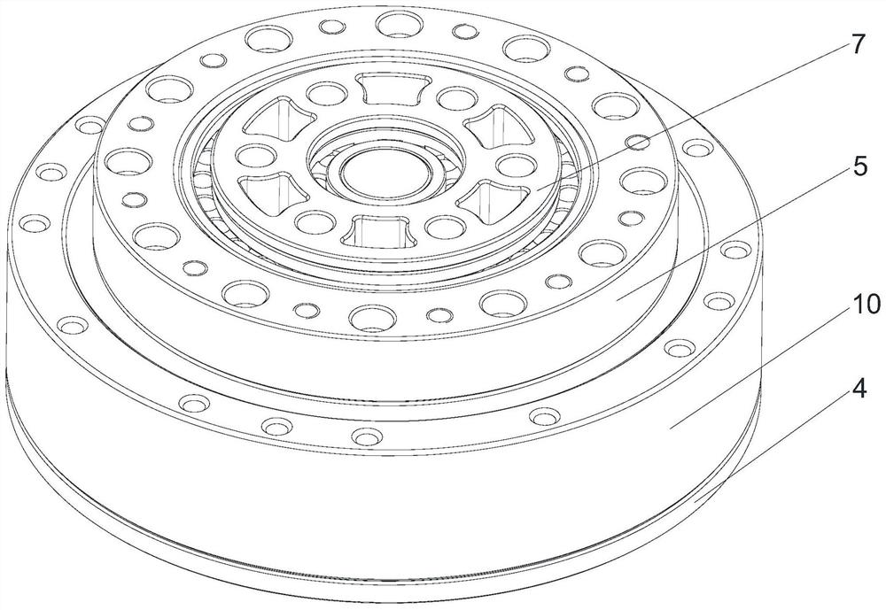
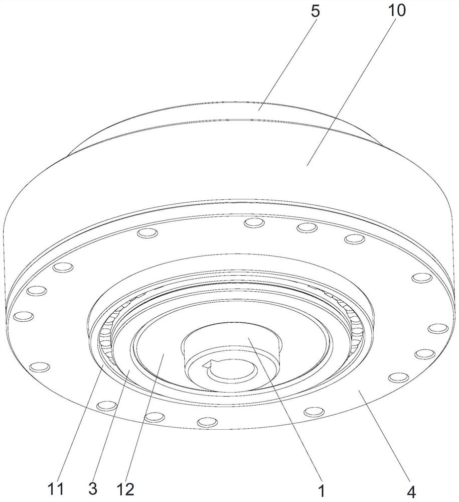
[0035] Such as Figure 1-Figure 7 As shown, a self-locking planetary reducer includes an inner gear ring, a sun gear 1, a planetary gear 2 and a planet carrier 3; The output inner gear ring 5 above the gear ring 4, the number of teeth of the fixed inner gear ring 4 is greater than or smaller than the number of teeth of the output inner gear ring 5; The gear ring 4 meshes with the output inner gear ring 5; the sun gear 1 is fixed at the center of the inner gear ring and meshes with the inner side of the planetary gear 2; one end of the sun gear 1 is used to connect with a power source so that when the sun gear 1 rotates Drive the planetary gear 2 to rotate along the inner ring of the fixed inner gear ring 4 and the output inner gear ring 5, and synchronously drive the output inner gear ring 5 to rotate and output power. Specifically, the power source is a driving motor, and the lower end of the sun gear 1 is a flower key and the spline is used to connect the power source. In ...

Embodiment 2

[0047] Such as Figure 8 As shown, a self-locking planetary reducer includes an inner gear ring, a planetary gear 2 and a planet carrier 33; the inner gear ring includes a fixed inner gear ring 4, and is used for power output and is located above the fixed inner gear ring 4 The output internal gear ring 5, the number of teeth of the fixed internal gear ring 4 is greater than or less than the number of teeth of the output internal gear ring 5; the planetary gear 2 is installed on the planet carrier 3 and the outer side of the planetary gear 2 is respectively connected to the fixed internal gear ring 4 and The output inner gear ring 5 meshes; the planetary carrier 3 is used to connect with a power source, so that when the planetary carrier 3 rotates, it drives the planetary gear 2 to rotate along the inner ring of the fixed inner gear ring 4 and the output inner gear ring 5, and drives the output inner gear ring synchronously. Ring gear 5 rotates to output power. In the present...


PUM


Abstract

The invention discloses a self-locking planetary reducer. The self-locking planetary reducer comprises an inner gear ring, a sun gear, a planet wheel and a planet carrier. The inner gear ring comprises a fixed inner gear ring body and an output inner gear ring body used for power output and located above the fixed inner gear ring body. The number of gear teeth of the fixed inner gear ring body isgreater than or smaller than the number of gear teeth of the output inner gear ring body. The planet wheel is mounted on the planet carrier and the outer side of the planet wheel is engaged with the fixed inner gear ring body and the output inner gear ring body. The sun gear is fixed to the center of the inner gear ring body and is engaged with the inner side of the planet wheel. One end of the sun gear is used for being connected with a power source, so that the sun gear drives the planet wheel to rotate along the inner rings of the fixed inner gear ring body and the output inner gear ring body when rotating, and the output inner gear ring body is synchronously driven to rotate and output power. The self-locking planetary reducer has the beneficial effects that the structure is simple, the gear modulus of the self-locking planetary reducer can be made larger compared with other reducers under the same deceleration ration and the same size, the impact force is strong, the service lifeis long, the torque is large, the positioning precision is high, the vibration is small, the reduction ratio is larger, and the repeated positioning precision is high.

Description

technical field [0001] The invention relates to the technical field of reducers, in particular to a self-locking planetary reducer. Background technique [0002] In the field of mechanical technology, the reducer is an independent closed transmission device between the prime mover and the working machine. Used to reduce speed and increase torque to meet work needs. [0003] At present, the core driver of Industry 4.0 is industrial automation, which aims to facilitate the flat integration of industry and life. As an indispensable key to Industry 4.0, industrial robots have formed an industrial chain with great potential. As one of the core components of industrial robots, the reducer located at the joint of the robot has become a hot high-tech industry at home and abroad because of its high technology, high added value, and high rate of return. However, these reducers still have disadvantages such as complex structure, low positioning accuracy and low transmission efficien...

Claims


Application Information

Patent Timeline
IPC IPC(8): F16H1/32F16H57/021
CPCF16H1/32F16H57/021
Inventor 何金仙
Owner 何金仙
Learn More