Thyristor converter valve base electronic equipment test system

A technology of valve-based electronic equipment and thyristor converter valves, which is applied in the field of thyristor converter valve-based electronic equipment testing systems, can solve problems such as project delays, difficulty, and inability to provide interface signal types and logical combinations.

Pending Publication Date: 2020-10-20
NR ELECTRIC CO LTD +1
View PDF0 Cites 0 Cited by
  • Summary
  • Abstract
  • Description
  • Claims
  • Application Information

AI Technical Summary

Problems solved by technology

At present, the factory process mainly tests the boards in the valve-based electronic equipment. This test method can neither provide the same signal type and logic combination of the upper and lower interfaces as the field, nor can it verify the functions of the entire set of valve-based electronic equipment.
The function of the whole set of valve-based electronic equipment and the comprehensive verification of the upper and lower interfaces can only be completed through third-party laboratory joint debugging or even on-site debugging after leaving the factory. , may even cause delays in the construction period
At present, there is no in-factory test system suitable for valve-based electronic equipment, which can fully test the upper and lower interfaces of the whole set of valve-based electronic equipment and the functions of the entire set of equipment before leaving the factory. This case is based on this demand.

Method used


Image

  • Thyristor converter valve base electronic equipment test system
  • Thyristor converter valve base electronic equipment test system

Examples


Embodiment Construction

[0022] The technical solutions and beneficial effects of the present invention will be described in detail below in conjunction with the accompanying drawings.

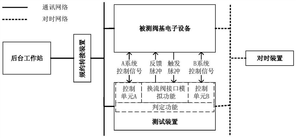
[0023] Such as figure 2 As shown, the present invention provides a thyristor converter valve valve base electronic equipment (referred to as VBE) testing system, including a background workstation, a network protocol conversion device, a timing device and a testing device, which are respectively introduced below:

[0024] The testing device provides a signal interface for the tested valve-based electronic equipment, and judges whether the function of the tested valve-based electronic equipment is normal according to the preset judgment logic. The testing device can complete the function simulation of the converter valve control unit in the redundant configuration mode, Implement active / standby mode switching.

[0025] The test device has the function of judging and outputting the operating state of the VBE device un...


PUM


Abstract

The invention discloses a thyristor converter valve base electronic equipment test system, which is characterized in that a test device provides a signal interface for tested valve base electronic equipment and judges whether the function of the tested valve base electronic equipment is normal or not according to preset judgment logic; the test device, the time synchronization device and the tested valve base electronic equipment are connected to a background communication network, a protocol conversion device converts various types of protocols and then is connected to a background workstation after conversion, and therefore the communication network is formed; the background workstation is provided with a man-machine interaction terminal, collects operation information of the accessed device through a communication network, and provides a man-machine interaction function according to the collected information; and the time synchronization device provides time synchronization signalsof various protocols. According to the system, thyristor converter valve base electronic equipment can be comprehensively tested in a delivery test stage, whether the performance and the function logic of the valve base electronic equipment meet the system design requirements or not is checked before the field test, faults of the tested equipment are found and eliminated in time, and the reliability of the valve base electronic equipment is improved.

Description

technical field [0001] The invention belongs to the field of power systems and power electronics in which thyristors are power devices, and particularly relates to a thyristor converter valve base electronic equipment testing system. Background technique [0002] In power system and power electronics related projects, valve-based electronic equipment, as an important part of the converter valve system, plays a connecting role. Such as figure 1 As shown, the valve-based electronic equipment is connected to the converter control unit on the upper side for control signal interaction; the lower side is connected to the thyristor converter valve, and receives the voltage state feedback pulse sent by the thyristor converter valve through the interface optical fiber and commutates the current to the thyristor. The valve sends out a trigger pulse, which realizes the control and monitoring function of the thyristor. [0003] In the actual project implementation process, there is no...

Claims


Application Information

Patent Timeline
Patent Type & Authority Applications(China)
IPC IPC(8): G01R31/26
CPCG01R31/263
Inventor 潘卫明崔恒丰刘磊王永平张翔
Owner NR ELECTRIC CO LTD
Why Eureka
Try Eureka