
Microseism ground monitoring device and seismic source positioning method

A monitoring device and source location technology, which can be used in measurement devices, seismology, geophysical measurements, etc.

Pending Publication Date: 2020-10-20
CENT FOR HYDROGEOLOGY & ENVIRONMENTAL GEOLOGY CGS
View PDF3 Cites 7 Cited by
  • Summary
  • Abstract
  • Description
  • Claims
  • Application Information

AI Technical Summary

Problems solved by technology

However, this technical solution has the following disadvantages: (1): This technical solution uses the method of picking up the first arrival of events, which is generally used for microseismic events in wells, and is not suitable for on-site ground monitoring
(2): This technical solution is based on the wireless data transmission system of WLAN, which has great limitations in the wild, and it is easy to disconnect the network due to climate, environment, antenna erection, etc.
Usually, the same-type wave or longitudinal and transverse waves used in deep well monitoring are used to extract the time difference of the first arrival to calculate the source position, which requires high-quality signals with a high signal-to-noise ratio. For ground monitoring, microseismic signals are transmitted from a depth of three to four kilometers underground. Near the ground, the energy is usually attenuated sharply, so the time-of-flight method is generally not suitable for ground station monitoring.

Method used


Image

  • Microseism ground monitoring device and seismic source positioning method
  • Microseism ground monitoring device and seismic source positioning method
  • Microseism ground monitoring device and seismic source positioning method

Examples


Embodiment Construction

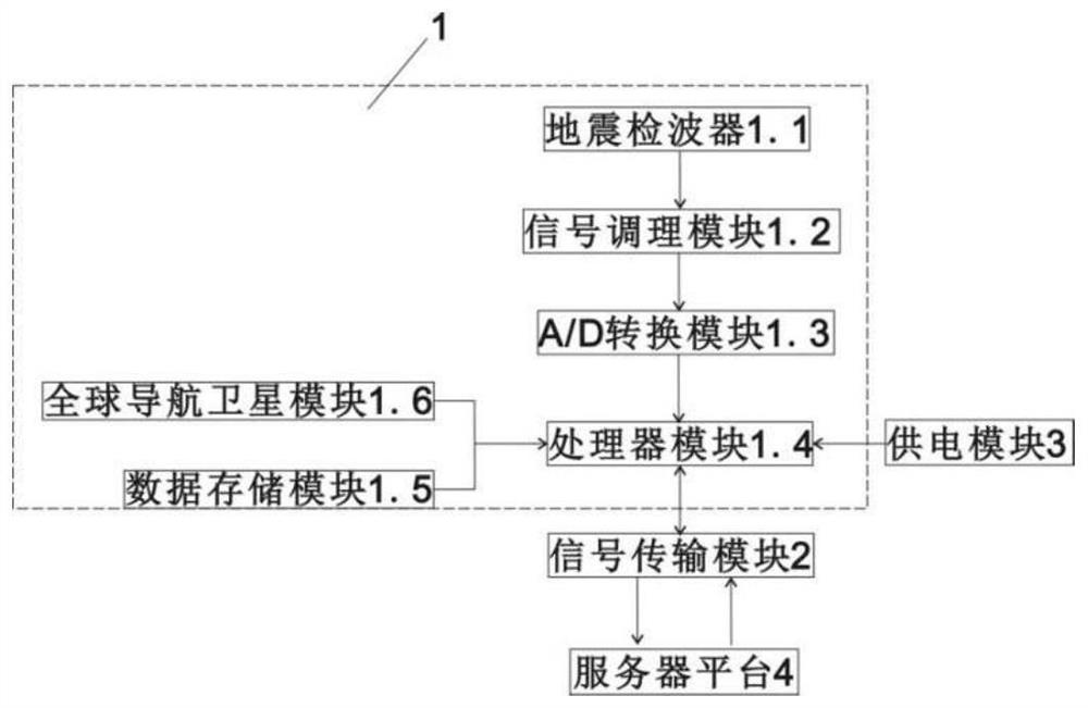
[0026] Such as figure 1 As shown, a microseismic ground monitoring device includes a data acquisition and processing module 1 , a signal transmission module 2 , and a power supply module 3 .

[0027] The data acquisition and processing module 1 includes a geophone 1.1, the geophone 1.1 is used to receive micro-seismic analog signals, the geophone 1.1 is connected to the signal conditioning module 1.2, and the signal conditioning module 1.2 is connected to the A / D conversion module 1.3, A / D The conversion module 1.3 is connected to the processor module 1.4.

[0028] The processor module 1.4 is respectively connected to the data storage module 1.5 and the global navigation satellite module 1.6.

[0029] The processor module 1.4 is connected to the signal transmission module 2, and the signal transmission module 2 is used for real-time connection with the server platform 4 through the wireless network, and the server platform 4 adopts a cloud server or a local server.

[0030] ...


PUM


Abstract

The invention discloses a microseism ground monitoring device and a seismic source positioning method. The microseism ground monitoring device comprises a data acquisition and processing module, a signal transmission module and a power supply module. The data acquisition and processing module comprises a geophone used for receiving a microseism analog signal; the geophone is connected with a signal conditioning module, which is connected with an A / D conversion module; the A / D conversion module is connected with a processor module, which is respectively connected with a data storage module anda global navigation satellite module; the processor module is connected with the signal transmission module; and the power supply module is connected with the data acquisition and processing module and is used for supplying power to the data acquisition and processing module. According to the invention, a superimposed energy scanning imaging technology which does not need to extract the first arrival of a signal event is adopted to carry out ground seismic source positioning, and the seismic source position can be effectively determined on the premise of not high requirement on signal source quality; microseism real-time positioning and monitoring can be supported through the server; and meanwhile, a mobile 4G signal is adopted, and the advantage of low signal transmission cost is achieved.

Description

technical field [0001] The invention relates to the technical field of microseismic monitoring, in particular to a microseismic ground monitoring device and a seismic source positioning method. Background technique [0002] Microseismic monitoring technology originated from the physical phenomenon of acoustic waves emitted by loaded rocks, and has been verified in a large number of laboratory and field experiments. At present, hydraulic fracturing has been widely used in the development of unconventional energy sources such as shale oil and gas reservoirs, hot dry rocks, and coalbed methane. Microseismic monitoring technology uses the vibration signals generated by fracturing to be picked up from the deployed microseismic detectors, and through superimposed energy scanning analysis and other positioning processing technologies, it provides the spatial form of fractures and monitors the scale and shape of artificial reservoirs formed by hydraulic fracturing. and fracture net...

Claims


Application Information

Patent Timeline
IPC IPC(8): G01V1/28G01V1/30G01V1/20
CPCG01V1/20G01V1/288G01V1/30
Inventor 吴悦杨凯郭伟李鹏王晨辉董翰川
Owner CENT FOR HYDROGEOLOGY & ENVIRONMENTAL GEOLOGY CGS
Learn More