Supercharge Your Innovation With Domain-Expert AI Agents!

Rotary electric machine

A technology of rotating electrical machines and rotating components, applied in the manufacture of such machines, the field of rotating electrical machines

Pending Publication Date: 2020-10-20
SPAL AUTOMOTIVE
View PDF1 Cites 0 Cited by
  • Summary
  • Abstract
  • Description
  • Claims
  • Application Information

AI Technical Summary

Problems solved by technology

[0011] Disadvantageously, this solution prevents access to the interior space for operations that may be required after the enclosure has been sealed

Method used


Image

  • Rotary electric machine
  • Rotary electric machine
  • Rotary electric machine

Examples


Embodiment Construction

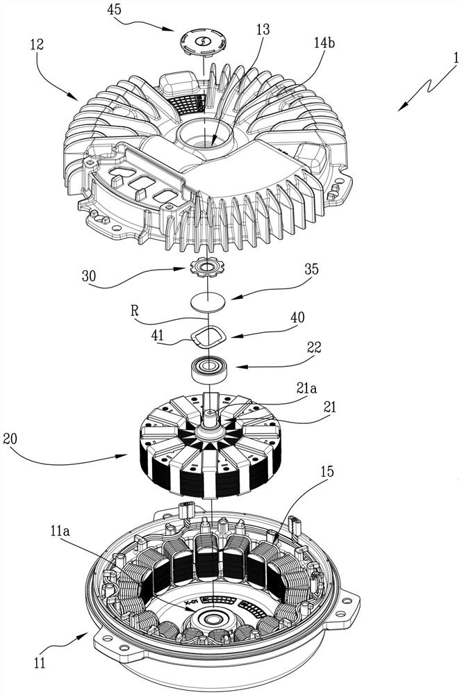
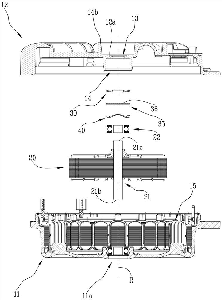
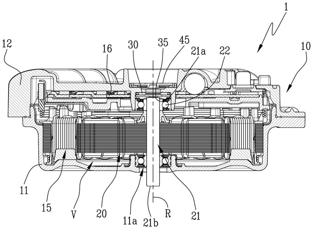
[0024] Referring to the drawings, a rotating electrical machine according to the present disclosure is generally denoted by reference numeral 1, and is hereinafter simply referred to as "electrical machine 1".

[0025] The electric machine 1 is preferably a canned electric machine, and reference is also made explicitly to this type of electric machine without thereby losing generality.

[0026] The electric machine 1 comprises a housing 10 delimiting an inner space "V".

[0027] In a preferred embodiment, the housing 10 includes a housing 11 and a cover 12 secured to the housing 11 to seal the gap therebetween to define an interior space "V".

[0028] The inner volume "V" accommodates a stator unit 15 fixed to the housing 11 and comprising a plurality of electrically conductive windings.

[0029] The inner volume "V" at least partially accommodates a rotor unit 20 magnetically associated with the stator unit 15 to define a brushless motor.

[0030] The electric machine 1 com...


PUM


Abstract

The present invention provides a rotary electric machine. The rotary electric machine (1) comprises an enclosure (10) delimiting an internal space (V) for containing a stator unit (15) and a rotor unit (20) coupled to the stator unit (15), the enclosure (10) being provided with an access hole (13) giving access to the internal space (V); a gasket (30) disposed inside the internal space (V) at a position adjacent to a wall (12a) of the enclosure (10) in such a way as to encircle the access hole (13); a closing element (35) disposed in the internal space (V), movable towards and away from the wall (12a) between a closed configuration in which it compresses the gasket (30) to seal the access hole (13) and an open configuration in which it places the internal space (V) in fluid communication with the surrounding atmosphere through the access hole (13); elastic means (40) operating on the closing element (35) to move the closing element (35) from the open configuration to the closed configuration and to compress the gasket (30) between the closing element (35) and the wall (12a) to seal the access hole (13). The closing element (35) has a pressure surface (36) facing the access hole (13) and accessible through the access hole (13) by means of a pin (S). Pressing the pressure surface (36) causes the closing element (35) to move from the closed configuration to the open configuration.

Description

technical field [0001] The invention relates to the technical field of motors. [0002] More specifically, the invention relates to a rotating electrical machine and a method for manufacturing such a machine. Background technique [0003] In general, this description also refers without loss of generality to the technical term referred to as "sealed" motors, that is to say without excluding machines referred to as "open" machines, unless otherwise stated. [0004] The term "hermetic rotating electrical machine" is used to denote a hermetic electrical machine comprising a hermetic container (or casing), usually consisting of a housing and a cover hermetically secured thereto, and the shaft of the rotor unit and the shaft for driving and The terminals that control the machine protrude from it. [0005] The main advantage of a sealed motor is that it isolates the moving parts and electronic control circuitry inside the vessel from foreign agents such as liquids and dust that ...

Claims


Application Information

Patent Timeline
IPC IPC(8): H02K5/10H02K5/124H02K5/16H02K15/14
CPCH02K5/10H02K5/124H02K5/16H02K15/14H02K5/173H02K5/1732H02K2205/09H02K11/33F04D25/082F04D29/5813H02K5/15H02K5/1672
Inventor 彼得罗·德菲利皮斯
Owner SPAL AUTOMOTIVE
Features
  • R&D
  • Intellectual Property
  • Life Sciences
  • Materials
  • Tech Scout
  • Unparalleled Data Quality
  • Higher Quality Content
  • 60% Fewer Hallucinations
Learn More