
Oscillator circuit arrangement

A circuit device, oscillator technology, applied in power oscillators, electrical components, generating electrical pulses, etc., can solve problems such as information interference, oscillation loss, and inability to recover by itself

Pending Publication Date: 2020-10-20
AMS AG
View PDF0 Cites 0 Cited by
  • Summary
  • Abstract
  • Description
  • Claims
  • Application Information

AI Technical Summary

Problems solved by technology

Oscillations can stop for a certain amount of time and resume later, or in the worst case, oscillations can be lost entirely and may not recover on their own
Therefore, the display of information in the electronic shelf label may be disturbed by EMI, or the label may be disturbed to stop working

Method used


Image

  • Oscillator circuit arrangement
  • Oscillator circuit arrangement
  • Oscillator circuit arrangement

Examples


Embodiment Construction

[0023] It is to be understood that both the foregoing general description and the following detailed description are exemplary only, and are intended to provide an overview or framework for understanding the nature and character of the claims. The present disclosure will now be described more fully herein with reference to the accompanying drawings that illustrate preferred embodiments of the disclosure. However, this disclosure may be embodied in many different forms and should not be construed as limited to the embodiments set forth herein. Rather, these embodiments are provided so that this disclosure will fully convey the scope of the disclosure to those skilled in the art. The drawings are not necessarily drawn to scale, but are configured to clearly illustrate the present disclosure. Identical elements in different figures are denoted by the same reference numerals.

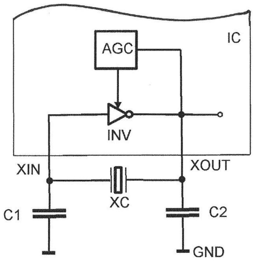
[0024] figure 1 A schematic diagram of a general oscillator is shown. The inverter INV is provided o...


PUM


Abstract

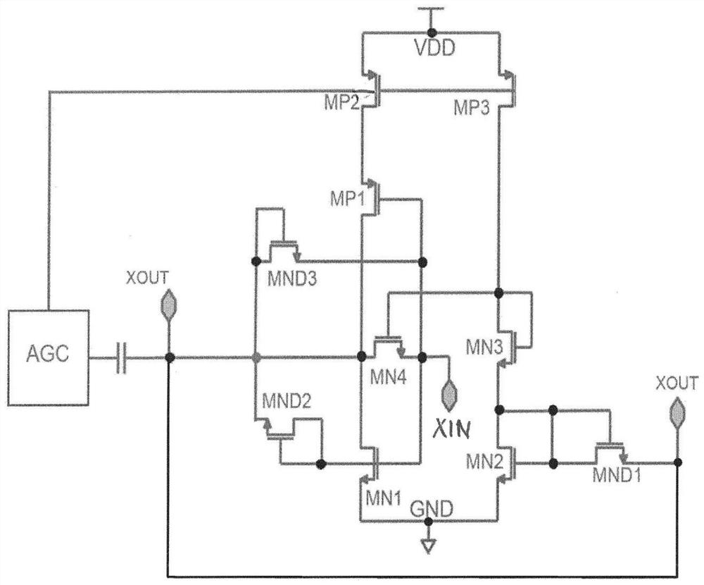
An oscillator circuit arrangement comprises an inverter having input and output terminals (XIN, XOUT) that are to be connected to a crystal device. An automatic gain control device (AGC) controls a current source (MP2) that supplies current to the inverter. First and second diode devices (MND2, MND3) having different orientation are connected between the input and the output of the inverter. The oscillator consumes low power and has a fast recovery time after an electromagnetic interference event. The oscillator can be used in electronic labels.

Description

technical field [0001] The present disclosure relates to an oscillator circuit arrangement for low power applications. In particular, the present disclosure relates to an oscillator circuit arrangement comprising an inverter to be connected to a crystal device and an automatic gain control device controlling a supply current to the inverter. The present disclosure also relates to the application of the oscillator circuit device in electronic tags. Background technique [0002] Oscillators are widely used to provide clock signals to control the operation of electronic devices. An oscillator can be implemented by an integrated circuit on a semiconductor chip with an external component such as a crystal to provide the time base and capacitors to provide the appropriate phase shift of the signal. [0003] Oscillators according to the Pierce architecture can be used in fields such as electronic tag or electronic paper applications where power consumption is critical. Electroni...

Claims


Application Information

Patent Timeline
Patent Type & Authority Applications(China)
IPC IPC(8): H03K3/013H03K3/014
CPCH03K3/013H03K3/014H03B5/364H03B2200/0012H03B2200/0094H03K3/3545
Inventor 拉希姆·阿克巴里-迪尔马加尼
Owner AMS AG
Learn More