
Electric push percussion device for percussing anastomat and electric anastomat

A stapler and electric technology, applied in anatomical instruments, medical science, surgery, etc., can solve the problems of anastomotic leakage, large differences in grip strength, and cumbersome manual operation steps.

Pending Publication Date: 2020-10-23
武汉智瓴医疗科技有限公司
View PDF6 Cites 11 Cited by
  • Summary
  • Abstract
  • Description
  • Claims
  • Application Information

AI Technical Summary

Problems solved by technology

Usually, the manual operation steps are cumbersome, and different operators will cause different distances between the nail anvil 1 and the staple cartridge, that is, the clamping degree of the tissue is different when the anastomosis is to be performed, and the grip strength of different people varies greatly. Unevenness can easily lead to poor nailing effect, resulting in anastomotic leak or anastomotic bleeding

Method used


Image

  • Electric push percussion device for percussing anastomat and electric anastomat
  • Electric push percussion device for percussing anastomat and electric anastomat
  • Electric push percussion device for percussing anastomat and electric anastomat

Examples


Embodiment 1

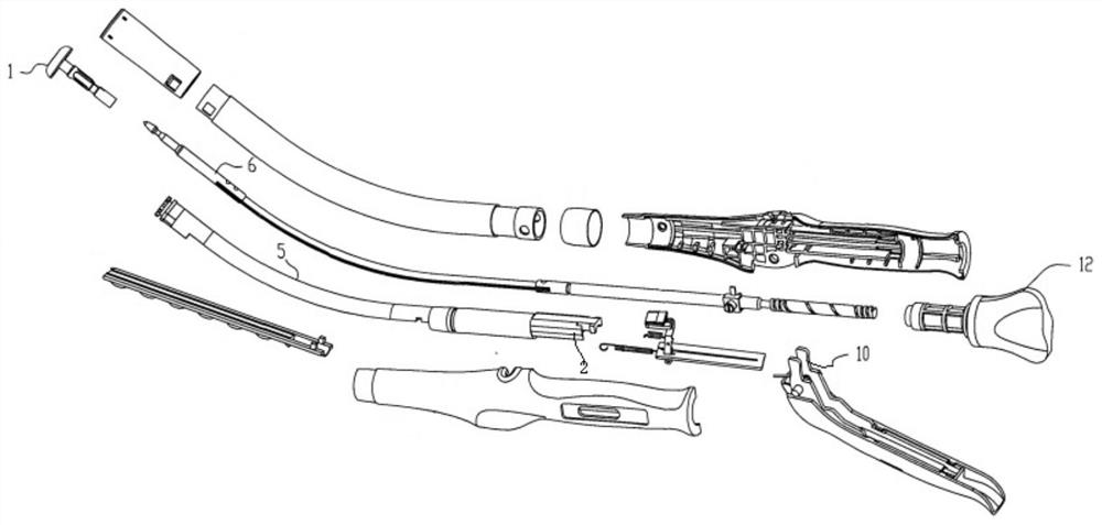
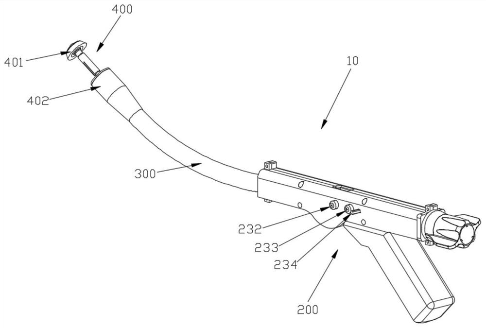
[0026] figure 2 An exemplary powered stapler 10 is shown for use in providing end-to-end stapling between two segments of an anatomical lumen, such as a portion of a patient's digestive tract. The surgical instrument 10 of this example includes a handle assembly 200 , a shaft tube 300 and an end effector 400 , wherein the end effector 400 includes a nail anvil 401 and a nail cartridge 402 . Shaft tube 300 extends distally from handle assembly 200 , and end effector 400 is coupled to the distal end of shaft tube 300 . Briefly, the handle assembly 200 is operable to actuate the end effector 400, selectively open and close the anvil 401 to clamp tissue between the anvil and the cartridge, and drive the staple cartridge 402. The cutting knife and staples in the knife cut through the tissue while the staples pass through the grooves of the tissue against the abutment to suture the tissue contained between the anvil and the staple cartridge.

[0027] image 3 Handle assembly 200...

Embodiment 2

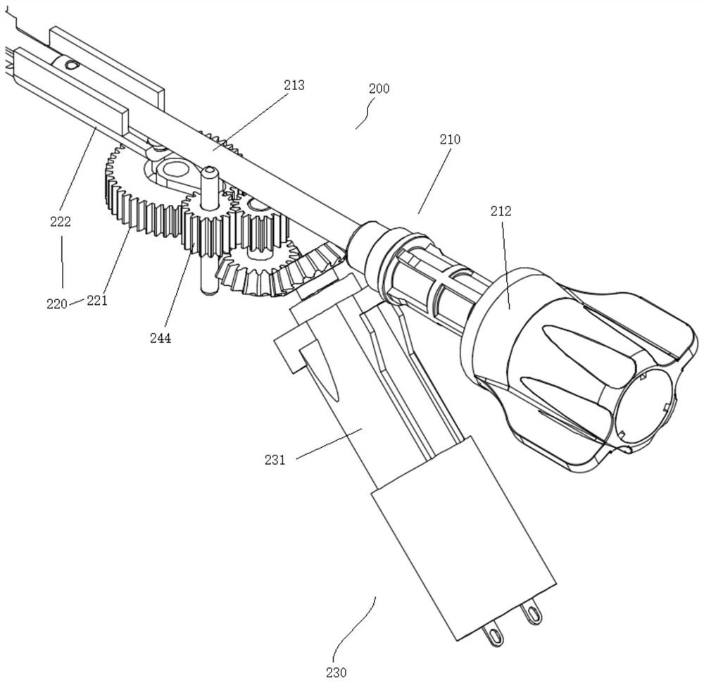
[0031] The electric stapler 10 includes a firing assembly 220 composed of a firing push rod 222 , a firing gear 221 , a pin 2214 , and a shaft 2212 in Embodiment 1, and a closing assembly 210 composed of a screw rod 213 and an adjusting nut 212 .

[0032] Such as Figure 7 The closure assembly 210 includes a threaded rod 213 , a rack 211 sleeved on a distal end of the threaded rod, and an adjusting nut 212 connected to a proximal end of the threaded rod 213 . The proximal end of the screw mandrel 213 is provided with a variable-pitch screw thread, and the adjusting nut 212 matches the thread of the screw mandrel 213. The rotation of the adjusting nut 212 will cause the screw mandrel 213 to move to the proximal end or the far end, and then control the screw mandrel 213 to be connected. The nail anvil 401 performs the clamping action of opening or closing. The variable pitch makes the anvil 401 move at different speeds in the longitudinal direction. When the adjusting nut 212 i...

Embodiment 3

[0040] Such as Figure 10 , the electric stapler 10 includes a firing assembly 220 composed of a firing push rod 222, a firing gear 221, a pin 2214, and a shaft 2212 in Embodiment 2, and a closing assembly 210 composed of a screw rod 213, and includes a plectrum 251, a positioning shaft 245, the driving assembly of transmission gear 244 and spring 252, the difference is that in this embodiment, the coupling part on the screw mandrel 213 that coincides with the transmission gear 244 is the basin gear 214, and the inner circumference of the basin gear 214 is threadedly matched with the outer circumference of the screw mandrel 213 The two sides of the basin gear 214 are abutted and limited by the stoppers 216 integrally connected with the shell of the stapler. The right end surface of the basin gear 214 is provided with a gear ring 2141. After the transmission gear 244 is pushed upward by the toggle assembly, the transmission gear 244 can mesh with the gear ring 2141, so that the...


PUM


Abstract

The invention provides an electric push percussion device for percussing anastomat and the electric anastomat. The electric push percussion device comprises a handle assembly, a shaft assembly extending distally from the handle assembly, and an end effector arranged at the distal section of the shaft assembly. The handle assembly includes an electric drive assembly, a closing assembly, a percussion assembly and a toggle assembly. The electric drive assembly can electrically drive the closing assembly and the percussion assembly to clamp, cut and suture tissue. The handle assembly also includesa gear mechanism, and can realize single-motor control on the closing and percussion actions of the electric anastomat. The end effector includes a nail propping seat and a nail bin. The toggle assembly realizes switching between closing and percussion actions. The invention also provides a cam structure connected to the electric drive assembly. The electric drive assembly uses longitudinal forcegenerated by rotation of the cam structure to drive the percussion assembly.

Description

technical field [0001] The invention relates to the field of medical instruments, in particular to an electric pushing device and an electric stapler for firing a stapler. Background technique [0002] In some surgical operations (eg, colorectal, bariatric, thoracic, etc.), parts of the patient's gastrointestinal tract or esophagus are cut and removed, and the resected part needs to be anastomosed and sutured through end-to-end Side-to-side anastomosis rejoins together. This type of surgical instrument is anastomosed with double rows of cross-arranged staples. At the same time, a circular knife cuts off the excess tissue in the annular array of staples at the anastomosis, so that the anastomotic caliber is uniform in size, the mucosa is aligned neatly, and the anastomosis is fast. Reliable anastomosis with good hemostasis and blood supply. Traditional staplers are mechanical, see figure 1 For example, in the mechanical stapler introduced in the patent CN101856250B, the na...

Claims


Application Information

Patent Timeline
Patent Type & Authority Applications(China)
IPC IPC(8): A61B17/115A61B17/11A61B17/3209
CPCA61B17/1155A61B17/1114A61B17/3209
Inventor 冯庆敏刘胜林王琮刘海洋
Owner 武汉智瓴医疗科技有限公司
Learn More