Floating oil removing device

An oil slick, oil drain technology used to remove oil with a lighter specific gravity floating on the surface of a liquid. It can solve the problems of limited use, consumable consumables, low work efficiency, etc.

Inactive Publication Date: 2020-10-23
NINGXIA KOCEL MACHINE TOOL ACCESSORIES
View PDF13 Cites 1 Cited by
  • Summary
  • Abstract
  • Description
  • Claims
  • Application Information

AI Technical Summary

Problems solved by technology

[0004] Based on this, it is necessary to provide an oil slick removal device with an adjustable use range

Method used


Image

  • Floating oil removing device
  • Floating oil removing device
  • Floating oil removing device

Examples


Embodiment Construction

[0036] In order to facilitate the understanding of the present invention, the present invention will be described more fully below with reference to the associated drawings. Preferred embodiments of the invention are shown in the accompanying drawings. However, the present invention can be embodied in many different forms and is not limited to the embodiments described herein. On the contrary, the purpose of providing these embodiments is to make the disclosure of the present invention more thorough and comprehensive.

[0037] It should be noted that when an element is referred to as being “disposed on” another element, it may be directly on the other element or there may also be an intervening element. When an element is referred to as being "connected to" another element, it can be directly connected to the other element or intervening elements may also be present. The terms "vertical", "horizontal", "left", "right", "top", "bottom", "bottom", "top" and similar expressions...


PUM


Abstract

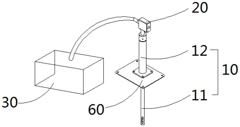
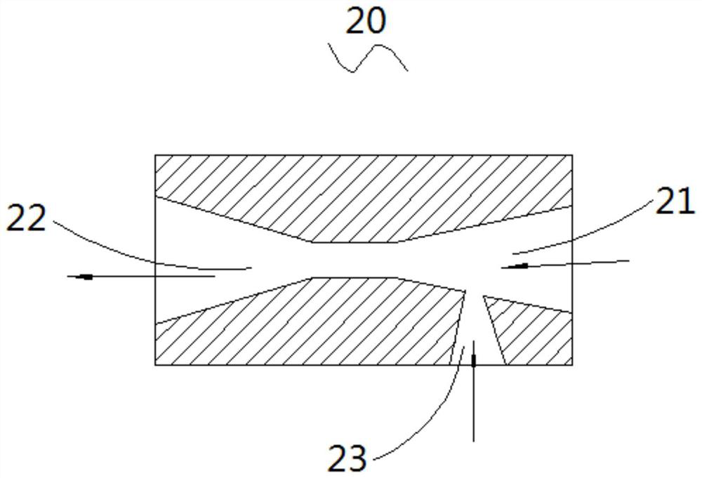
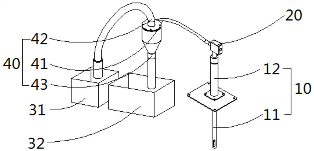
The invention discloses a floating oil removing device which comprises an oil suction assembly, a pneumatic device and an oil collection box, and the pneumatic device is provided with a gas inlet, anoil discharge port and an oil suction port; the gas inlet, the oil discharge port and the oil suction port are communicated with one another; the calibers of the oil discharge port and the oil suctionport are gradually reduced from outside to inside; the oil suction assembly comprises an oil suction pipe and an installation base arranged on the oil suction pipe in a sleeving mode. One end of theoil suction pipe is immersed into a liquid level, and the other end is connected with the oil suction port; the oil outlet is connected with the oil collecting box; the gas inlet is externally connected with a gas source; and the mounting base is fixed on the liquid tank. Compressed air is input at a certain pressure through the gas inlet, negative pressure can be formed in the space where the oiloutlet and the oil suction port intersect through reducing of the port, floating oil on the liquid level can be sucked into the oil suction pipe through the negative pressure and then discharged intothe oil collecting box through the oil outlet, and then removal of the floating oil on the liquid level is achieved.

Description

technical field [0001] The invention relates to the field of oil-water separation, and is mainly used for removing oil with light specific gravity floating on the liquid surface. Background technique [0002] In machine tool processing, various types of oil will enter the lubrication of the machine tool, resulting in the contamination of the cutting fluid, which will affect the machining accuracy and quality, and the cutting fluid cannot be reused. Therefore, it is necessary to use an oil-water separation device to separate and collect the floating oil, purify the cutting fluid, and realize the recycling of the cutting fluid. [0003] Commonly used oil-water separation devices include belt-type oil-water separation and disk-type oil-water separation, which need to be driven by a motor-driven transmission to drive the viscous oil belt or disk to run continuously to achieve oil separation. This solution not only consumes electric energy, but also the viscous oil belt or disc ...

Claims


Application Information

Patent Timeline
IPC IPC(8): B01D17/032
CPCB01D17/0214Y02A20/204
Inventor 王芬王小强赵焱赵亚宁何国峰孙冠琳黄建瑞李成成
Owner NINGXIA KOCEL MACHINE TOOL ACCESSORIES
Why Eureka
Try Eureka