
Distributed closed dry dust removal system and dust removal method in return air lane

A technology for dry dust removal and return air lanes, applied in separation methods, chemical instruments and methods, dust prevention and other directions, can solve the problems of large resistance of dust collectors, large spray water consumption, increase roadway resistance, etc., and reduce the resistance of dust collectors. , Increase the filtration efficiency and reduce the effect of filtering airflow

Active Publication Date: 2021-06-22
CHINA UNIV OF MINING & TECH
View PDF7 Cites 0 Cited by
  • Summary
  • Abstract
  • Description
  • Claims
  • Application Information

AI Technical Summary

Problems solved by technology

[0002] A large amount of dust will be generated during the coal cutting and coal falling process of the coal mining machine. The dust enters the return air lane from the coal mining face along with the wind, resulting in a large dust concentration in the return air lane. In addition, the air volume of the return air lane is relatively large, generally at 1500m 3 / min, the air volume is much larger than that of a single dry filter dust collector, and the dust is not easy to capture; in addition, the high wind speed makes it easy to raise the deposited dust again, and the concentration of respirable dust in the dust is large, which leads to return air The environment in the alley is deteriorating, and the visibility is low, which affects the normal operation of the equipment, and there are hidden dangers of coal dust explosion accidents. On the other hand, the concentration of respirable dust is high, which easily makes workers suffer from pneumoconiosis and threatens the lives and health of workers.
[0003] For a long time, coal mines have mainly used spray dust reduction and the combination of spray and screen for dust removal. There are usually the following problems: the use of spray spray consumes a lot of water, especially in Northwest China, coal mines are seriously short of water and cannot meet the normal water demand requirements ; High water quality requirements, when there are many impurities in the water, it is easy to cause nozzle blockage; when using spray for dust reduction, the dust removal efficiency is low, especially for respirable dust, the dust removal effect is not obvious
The combination of spray and screen is used to remove dust. On the one hand, the resistance of the roadway is increased. The main ventilator cannot meet the needs of mine ventilation. In order to ensure the normal operation of the mine, it is necessary to increase the energy consumption of the main ventilator and reduce the use of the main ventilator. Life, on the other hand, is not conducive to the normal passage of pedestrians and vehicles
[0004] A Chinese invention patent published on April 27, 2016, with a publication number of CN105525939A "a dry filter and dust removal system for roadway excavation working face", the system adopts the method of extracting ventilation, filtering and dust removal for dust removal. On the one hand, the extracting ventilation The effective dust collection is small, the negative pressure is low, and the dust removal effect is not good; on the other hand, the space of the coal mine roadway is narrow, and the volume of the dry dust collector needs to be as small as possible. The dust collector has a large resistance and a small filtering air volume, resulting in low dust removal efficiency; in addition, the current coal safety certified dry dust collector has a maximum air volume of 600m 3 / min, unable to match the air volume of the return air lane

Method used


Image

  • Distributed closed dry dust removal system and dust removal method in return air lane
  • Distributed closed dry dust removal system and dust removal method in return air lane
  • Distributed closed dry dust removal system and dust removal method in return air lane

Examples


Embodiment

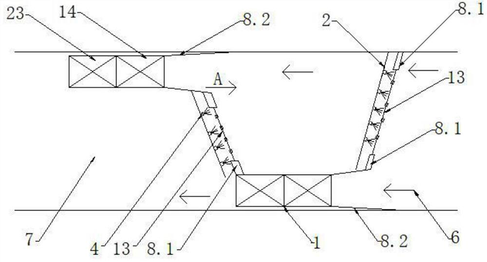
[0090] A distributed airtight dry dust removal system and a dust removal method for a return airway, the specific examples of which are as follows:

[0091] The total air volume Q of the return airway that needs to be treated 总 1500m 3 / min, front side dust collector processing air volume Q 1 Choose 600m 3 / min, the air volume Q of the rear side dust collector 3 Choose 500m 3 / min, you can obtain:

[0092] Front side filter handles air volume Q 2 =Q 总 -Q 1 =1500-600=900m 3 / min

[0093] Rear filter handles air volume Q 4 =Q 总 -Q 1 -Q 3 =1500-600-500=400m 3 / min

[0094] Resistance coefficient k of the selected front filter 2 is 1Pa·s / m, the drag coefficient k of the selected rear filter 4 2Pa·s / m, the filter area of ​​the front filter is s 2 20m 2 , the filter area s of the rear filter 4 19m 2 ,but

[0095] The initial resistances of the front and rear filters are:

[0096] P 02 =k 2 Q 2 / s 2 =1×900 / 20=45Pa

[0097] P 04 =k 4 Q 4 / s 4 =2×400 / 19=...


PUM


Abstract

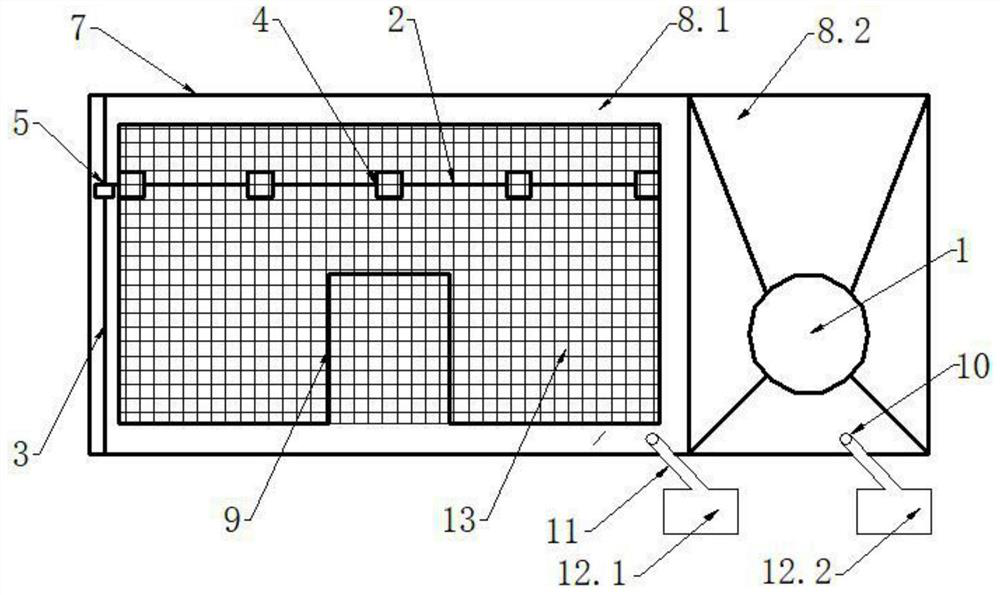
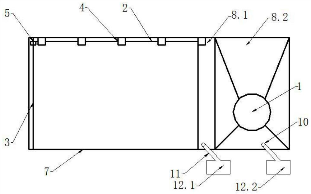
A distributed airtight dry dust removal system and dust removal method for a return air lane, the system is provided with two sets along the wind flow direction of the return air lane, one in front and one behind, and the dust collectors are arranged in a staggered manner along the roadway walls on both sides; Installed on the front side of the dust collector box, air holes are set on the air bag I and the air bag II, and the intelligent air extraction device I and the intelligent air extraction device II are respectively connected to the air holes through rigid pipes; the air bag I is set on the side away from the dust collector, There is a filter screen inside, the airbag I and the airbag II are used independently, the inflated airbag I is attached to the adjacent side of the airbag II, the opposite side of the airbag I and the airbag II is attached to the roadway wall, and the airbag of the rear dry dust removal system ⅠClose to the tail of the dust collector; the air pipe can be moved up and down and arranged on one side of the filter screen, and the high-pressure nozzle is arranged on the air pipe, and the high-pressure nozzle is directly facing the filter screen; High-efficiency and low-resistance dust removal, and no water is used in the dust removal process, and the dust removal effect is good.

Description

technical field [0001] The invention relates to a dry dust removal system, in particular to a distributed airtight dry dust removal system and a dust removal method for a return air lane, belonging to the technical field of coal mine roadway ventilation and dust removal. Background technique [0002] A large amount of dust will be generated during the coal cutting and coal falling process of the coal mining machine. The dust enters the return air lane from the coal mining face along with the wind, resulting in a large dust concentration in the return air lane. In addition, the air volume of the return air lane is relatively large, generally at 1500m 3 / min, the air volume is much larger than that of a single dry filter dust collector, and the dust is not easy to capture; in addition, the high wind speed makes it easy to raise the deposited dust again, and the concentration of respirable dust in the dust is large, which leads to return air The environment of the alley is dete...

Claims


Application Information

Patent Timeline
Patent Type & Authority Patents(China)
IPC IPC(8): B01D50/00B01D46/00B01D46/24B01D46/10E21F5/04E21F5/00E21F5/20
CPCB01D46/2411B01D46/10E21F5/04E21F5/00E21F5/20B01D46/681B01D50/60
Inventor 李世航周福宝刘浩谭晓宇户书达靳昊谢彪王路宇温国祥
Owner CHINA UNIV OF MINING & TECH
Learn More