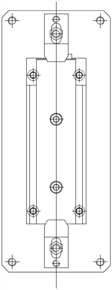
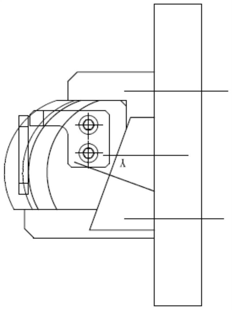
Machining method for assembling surface of dehumidifying blade

A blade assembly and surface processing technology, applied in the field of mechanical processing, can solve the problems of poor blade profile, easy bowing, and affecting welding quality

Active Publication Date: 2020-10-23
HARBIN TURBINE +1
View PDF10 Cites 2 Cited by
  • Summary
  • Abstract
  • Description
  • Claims
  • Application Information

AI Technical Summary

Problems solved by technology

[0003] The present invention solves the problem that the existing dehumidification blades are clamped at both ends during processing, which is easy to bow and deform, resulting in poor profile of the blade surface. During assembly, a fitter is required to eliminate the gap. Reproduce the gap and affect the welding quality, and then provide a method for processing the assembly surface of the dehumidification blade;

Method used


Image

  • Machining method for assembling surface of dehumidifying blade
  • Machining method for assembling surface of dehumidifying blade
  • Machining method for assembling surface of dehumidifying blade

Examples


specific Embodiment approach 1

[0039] Specific Embodiment 1: This embodiment provides a method for processing the assembly surface of a dehumidification blade, which is characterized in that: the method is realized through the following steps:

[0040] Step 1: Select the blank: Compared with the ordinary blank, the selected blank has a 7mm process head margin at the root of the blade, and a 5mm process head margin at the end face of the blade crown;

[0041] Step 2: Machining reference plane: use horizontal milling machine and flat grinding machine to process; first use horizontal milling machine to correct the blank selected in step 1, and process the blank with deviation in size into a cuboid blank, and then use flat grinding machine to grind To cut the six surfaces of the cuboid blank, the parallelism of both sides is required to be 0.02mm, and the dimensional tolerance is -0.03~0mm. The parallelism of the other two sides is 0.05 / 100, and the perpendicularity to both sides is 0.03 / 100. The perpendicular...

specific Embodiment approach 2

[0052] Specific embodiment 2: This embodiment is to further limit the step 2 described in the specific embodiment 1. In this embodiment, the cutting parameters of the horizontal milling machine tool used to correct the milling in the step 2 are: spindle speed: 800r / min , Feed speed: 40mm / min, depth of cut: 1-2mm, cutting parameters processed by flat grinding machine tools are: spindle speed: 26m / s, feed speed: 600mm / min; other components and connection methods and specific implementation methods One is the same.

specific Embodiment approach 3

[0053] Specific embodiment 3: This embodiment is to further limit the step 4 described in the specific embodiment 1. In this embodiment, in the step 4, a powerful grinding machine is used to finish the inner arc of the assembly, and the processing parameters of the fine milling are selected. :

[0054] Cutting depth 0.1mm 6 cutters, spindle speed 26m / s, feed speed 600mm / min;

[0055] Cutting depth 0.05mm 6 knives, spindle speed 26m / s, feed speed 600mm / min;

[0056] Cutting depth 0.02mm2 cutter, spindle speed 26m / s, feed speed 600mm / min;

[0057] Cutting depth 0.02mm 2 knives, spindle speed 26m / s, feed speed 600mm / min;

[0058] The depth of cut is 0.01mm, 2 knives, the spindle speed is 26m / s, and the feed rate is 600mm / min.

[0059] Other compositions and connection methods are the same as those in the second embodiment.

[0060] This embodiment adopts multi-feed grinding, and the single grinding amount is 0.1mm, 0.05mm, 0.02mm, 0.02mm, 0.1mm respectively. The cutting amoun...


PUM


Abstract

The invention discloses a machining method for an assembling surface of a dehumidifying blade, belongs to the field of machining methods, and aims to solve the problems that the profile tolerance of ablade profile is poor, a bench worker is required to eliminate a gap during assembly, the gap is reproduced when the end surface of a blade crown is assembled again through a beveling procedure and the welding quality is affected due to high probability of bowing and deformation when two ends are clamped in the machining process of the conventional dehumidifying blade. According to the machiningmethod, the clamping mode of an existing machining method for the assembling face of the dehumidifying blade is changed, the machining technological process is correspondingly changed, the margins oftwo-end technological sections are reserved when a workblank is selected, the two-end technological sections are clamped and machined through a clamp during machining, and therefore the defects of anexisting workpiece two-end clamping mode are effectively overcome. The machining method is mainly used for machining and manufacturing the assembling face of the dehumidifying blade.

Description

technical field [0001] The invention relates to the field of mechanical processing methods, in particular to a method for processing an assembly surface of a dehumidification blade. Background technique [0002] Regarding the blades of the dehumidification stage, they are circular arc surfaces, and the distance between the center of the circle and the air inlet and outlet sides is quite different, resulting in a large arc swing, and there is no overlapping surface on the inlet and outlet sides of the blades. The radial pitch of the blades is small and radially thin. It brings great difficulty to the processing and clamping of the blade. The previous processing adopts the method of clamping both ends, which is easy to bow and deform. As a result, the profile of the blade assembly surface is poor. During the pre-assembly, the gap between adjacent blades is out of tolerance, and the fitter needs to eliminate the gap. After the pre-assembly, the end face of the blade crown is r...

Claims


Application Information

Patent Timeline
Patent Type & Authority Applications(China)
IPC IPC(8): B23P15/02
CPCB23P15/02
Inventor 王红海孙珂庄乾才刘铁闫原车德建齐琳倩于华张卓然杨佳财
Owner HARBIN TURBINE
Why Eureka
Try Eureka