Material cooling conveyor with steel belt surface cleaning and protection functions

A technology for cooling conveyors and surface cleaning, which is applied to conveyors, conveyor objects, and devices for coating liquid on the surface, etc., and can solve problems such as poor reliability, slipping of supporting wheels, and affecting the heat transfer and cooling effect of the steel belt surface

Pending Publication Date: 2020-10-23
SHANGHAI RUIBAO GRANULATOR CO LTD
View PDF0 Cites 0 Cited by
  • Summary
  • Abstract
  • Description
  • Claims
  • Application Information

AI Technical Summary

Problems solved by technology

In the long-term application practice, it is found that although the high-temperature liquid molten material is loaded onto the steel belt, it will continue to evaporate, cool, and solidify into solid particle products that are easy to scrape off from the steel belt during the process of moving forward with the steel belt, but for Due to the influence of the mutual adhesion force on the part of the molten material that is loaded onto the surface of the steel belt and is in direct contact with the steel belt, some solid particle products are easily bonded to the steel belt and are difficult to be completely scraped off by the scraper, resulting in There are residual adhesions on the surface of the steel belt, which will not only affect the yield of molten materials, but also affect the cleanliness of the surface of the steel belt, and this residual adhesion will accumulate more and more during the cycle of the steel belt. In addition to directly affecting the heat transfer and cooling effect on the surface of the steel strip, thereby affecting the solidification and molding effect and efficiency of the p...

Method used


Image

  • Material cooling conveyor with steel belt surface cleaning and protection functions
  • Material cooling conveyor with steel belt surface cleaning and protection functions
  • Material cooling conveyor with steel belt surface cleaning and protection functions

Examples


Embodiment Construction

[0047] The present invention will be further described below in conjunction with the accompanying drawings and typical embodiments.

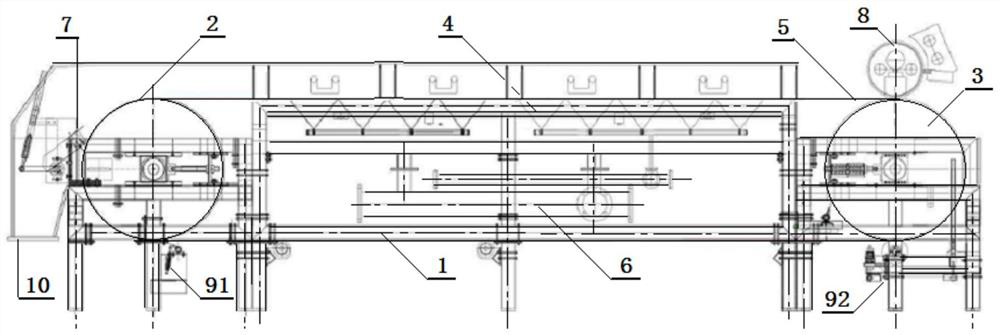
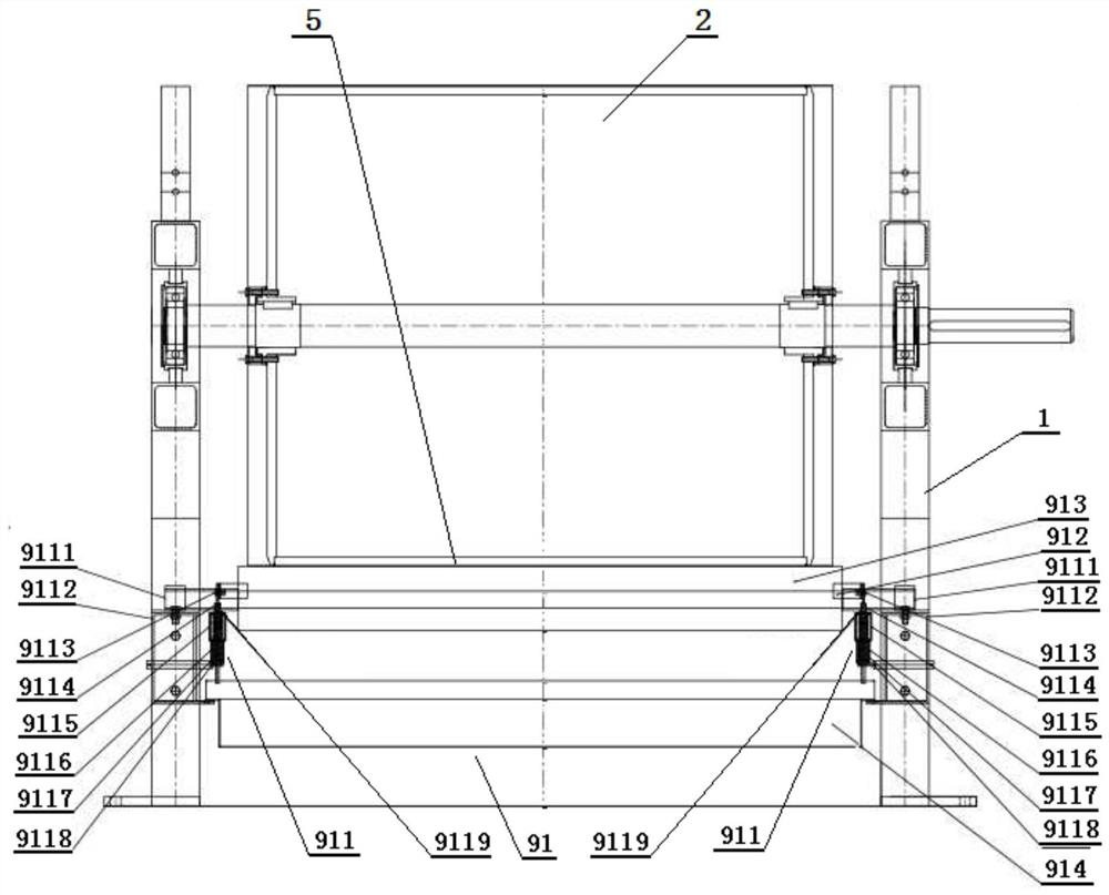
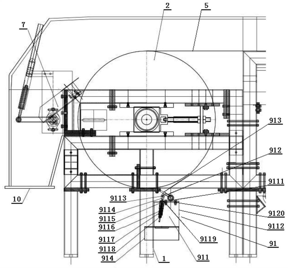
[0048] exist figure 1 Among them, a material cooling conveyor with the functions of cleaning and protecting the steel belt surface of the present invention mainly includes a frame 1, a main driving drum 2 and a driven tensioning drum 3 respectively arranged at the front and rear ends of the frame, and the The steel belt carrying platform 4 between the left and right side frames of the frame, the closed loop steel belt 5 arranged between the main driving drum 2 and the driven tensioning drum 3, and the water cooling cooling mechanism 6 arranged under the steel belt carrying platform 4, The molten material distributor 8 arranged above the driven tension drum 3, and the unloading scraper 7 and the unloading hopper 10 arranged on the side of the main driving drum 2 are characterized in that: it also includes a The steel belt surface cleaning mechan...


PUM


Abstract

The invention relates to a material cooling conveyor with steel belt surface cleaning and protection functions. The material cooling conveyor is characterized in that a steel belt surface cleaning mechanism and a steel belt protective release agent application mechanism are fixedly arranged on a return path of the steel belt circulating work in sequence, wherein the steel belt surface cleaning mechanism mainly includes a left/right tool rest limiting supporting seat, a tool rest, a scraper and a slag receiving box, and the steel belt protective release agent application mechanism mainly includes a left/right push-pull rod lifting mechanism, a water tank rubber roller mechanism and a left/right supporting mechanism of a water tank. The steel belt surface cleaning mechanism and the steel belt protective release agent application mechanism work synchronously with the operation of a steel belt, the steel belt protective release agent application mechanism has two working modes of applyingand non-applying of a protective release agent according to actual working conditions on the steel belt, so that the steel belt can be subjected to orderly heat transfer, promoting of the cooling of high-temperature molten materials, curing and evaporating of moisture in the protective release agent after being evenly applied with the protective release agent in a surface clean state, and thus theprotective release agent becomes a surface protective layer that facilitates the scrape-off of granular products and the normal working life of the steel belt.

Description

technical field [0001] The invention relates to the technical field of material cooling and conveying equipment, in particular to a steel belt surface cleaning and protection function, which can ensure the normal working life of the steel belt, the normal solidification of molten materials into conventional granular products, and avoid the final formed product from getting wet, which is beneficial to The steel belt material cooling conveyor with continuous and safe operation of the system, high efficiency and low cost output. Background technique [0002] In the production process of petrochemical oil refining and petrochemical industry, a large number of high-temperature liquid molten products will be produced, such as: molten liquid sulfur with a temperature of about 135 degrees, molten liquid petroleum resin and phenolic resin with a temperature of about 210 degrees, and temperature up to Melted liquid paraffin at about 58 degrees and rubber additives at 52 degrees, etc.,...

Claims


Application Information

Patent Timeline
IPC IPC(8): B65G15/48B65G23/04B65G23/44B65G69/20B65G45/12B65G45/26B05C1/02B05C13/02
CPCB05C1/02B05C13/02B65G15/48B65G23/04B65G23/44B65G45/12B65G45/26B65G69/20
Inventor 杨海波
Owner SHANGHAI RUIBAO GRANULATOR CO LTD
Why Eureka
Try Eureka