
Coal rock three-dimensional strain field visualization system and method under complex geological structure

A technology of complex geology and strain field, used in instruments, mechanical devices, teaching models, etc.

Pending Publication Date: 2020-10-23
CHONGQING UNIV
View PDF0 Cites 4 Cited by
  • Summary
  • Abstract
  • Description
  • Claims
  • Application Information

AI Technical Summary

Problems solved by technology

[0004] The purpose of the present invention is to provide a visualization system and method for the three-dimensional strain field of coal and rock under complex geological structures, so as to solve the problems existing in the prior art

Method used


Image

  • Coal rock three-dimensional strain field visualization system and method under complex geological structure
  • Coal rock three-dimensional strain field visualization system and method under complex geological structure
  • Coal rock three-dimensional strain field visualization system and method under complex geological structure

Examples


Embodiment 1

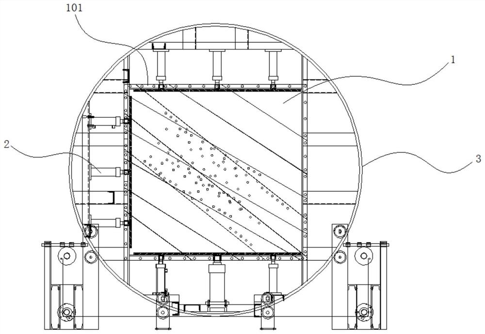
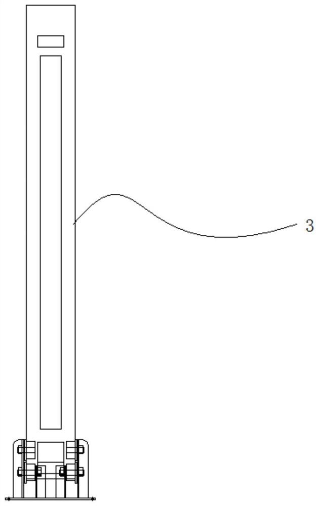
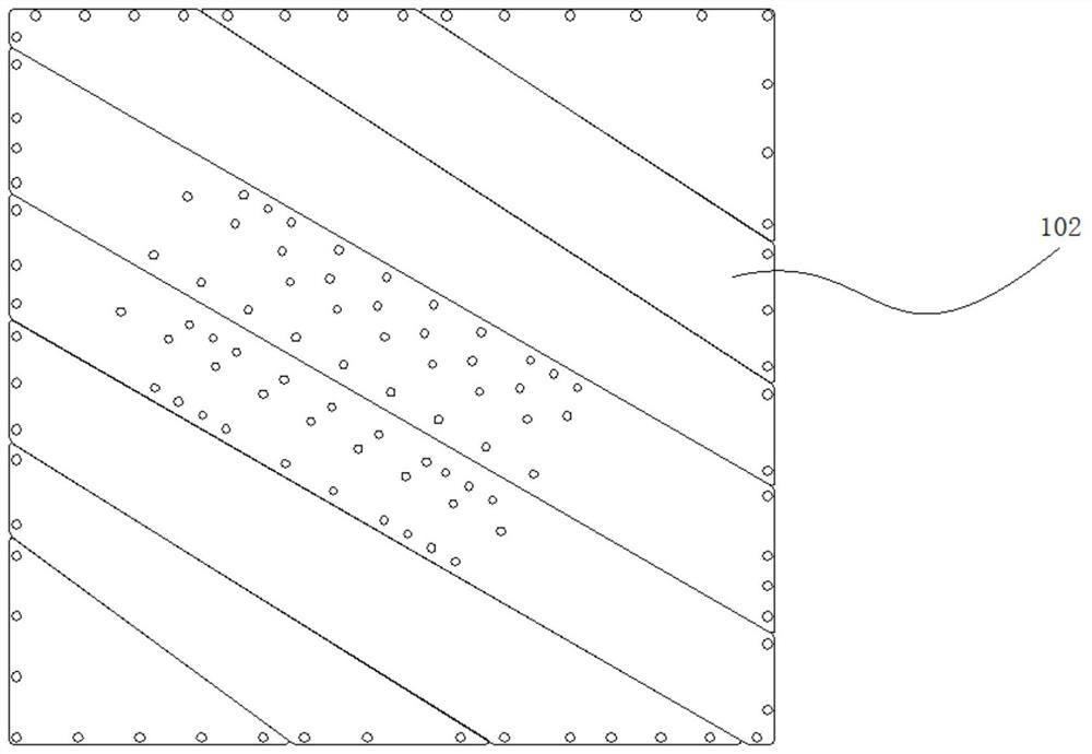
[0035] see Figure 1 ~ Figure 4 , this embodiment discloses a three-dimensional strain field visualization system for coal and rock under complex geological structures, including a stress condition simulation system and a strain monitoring system.

[0036] The stress condition simulation system includes a similar simulation experiment frame 1 , a loading system 2 and a circular slideway 3 .

[0037] The similar simulation experiment frame 1 includes a pressure chamber 101 and two visualization side panels 102 . The pressure chamber 101 is a rectangular frame as a whole. Openings at both ends of the rectangular frame are blocked by the visible side panels 102 . The pressure chamber 101 and the visualization side panel 102 enclose a model placement cavity.

[0038] The loading system 2 includes a vertical axial compression loading system and a horizontal stress loading system. The vertical axial pressure loading system loads a set vertical loading force on the top and bottom...

Embodiment 2

[0042] see Figure 4 , this embodiment discloses a method for visualizing the three-dimensional strain field of coal and rock under complex geological structures using the system described in Embodiment 1, including the following steps:

[0043] 1) Heat and melt the transparent base material and evenly mix it with ink microcapsules to prepare 3D printing filaments. The wall of the ink microcapsule is made of polyurethane material, and the core of the capsule is made of dyed ink. The transparent base material adopts organic silicon resin.

[0044] In this embodiment, the ink microcapsules are synthesized by chemical method. Chemical method, also known as in-situ polymerization method, refers to adjusting the temperature, pH value of the reaction system or adding electrolytes, catalysts and a series of reaction conditions, so that small monomer molecules polymerize to form polymer film-forming materials, and precipitate out of the solution , wrap the core material. In the wh...

Embodiment 3

[0055] The main steps of this embodiment are the same as those in Embodiment 2, wherein, in step 4), a larger stress is applied on the left side of the top of the coal seam, and a larger stress is applied on the right side of the bottom, acting on the model as the main shear stress, so that the model is in the shear stress. Faults are generated under the action of stress, simulating the situation near the fault geological structure of coal and rock mass.


PUM


Abstract

The invention provides a coal rock three-dimensional strain field visualization system and method under a complex geological structure. The system comprises a stress condition simulation system and astrain monitoring system. The stress condition simulation system comprises an analog simulation experiment frame, a loading system and a circular slideway. The method comprises the steps of preparinga 3D printing wire rod, printing a strain visualization similar model, simulating a stratum inclination angle and a gas-containing condition, applying a stress field, recording a micro-capsule ruptureand dyeing condition in the model and the like. The system can realize tracking of generation and development of cracks in a complex geological condition analog simulation model, and track three-dimensional movement of internal ink dots to draw a displacement field four-dimensional image.

Description

technical field [0001] The invention relates to the field of mechanical and mining technology engineering, in particular to a visualization system and method for a three-dimensional strain field of coal and rock under complex geological structures. Background technique [0002] As an important research method of rock formation control technology, similar simulation experiment has been widely accepted and recognized. However, in the traditional similar simulation experiment, it is impossible to observe the internal strain field distribution of the material intuitively, and to observe the internal strain through the indirect measurement method, not only there are large errors, but also the integrity of the model will be destroyed, resulting in unnecessary errors. By using transparent microcapsule composite materials to construct the model, the internal strain field distribution of the model can be observed directly and in real time without destroying the integrity of the model...

Claims


Application Information

Patent Timeline
Patent Type & Authority Applications(China)
IPC IPC(8): G01N19/00G01N33/24G09B23/40
CPCG01N19/00G01N33/24G09B23/40B33Y80/00B33Y10/00B33Y70/00G01N1/2806G01N3/068G01N3/08G01N2203/0019G01N2203/0066G01N2203/0254G01N2203/0652
Inventor 刘浩刘涵邹全乐冉启灿王睿智张碧川王智民陈子涵吴斐
Owner CHONGQING UNIV
Learn More