Liftable temporary storage container assembly for dismounting nuclear reactor detector assembly and method
A technology for detector components and nuclear reactors, applied in portable protective containers, nuclear engineering, etc., can solve the problems of less research on storage technology
- Summary
- Abstract
- Description
- Claims
- Application Information
AI Technical Summary
Problems solved by technology
Method used
Image
Examples
Embodiment 1
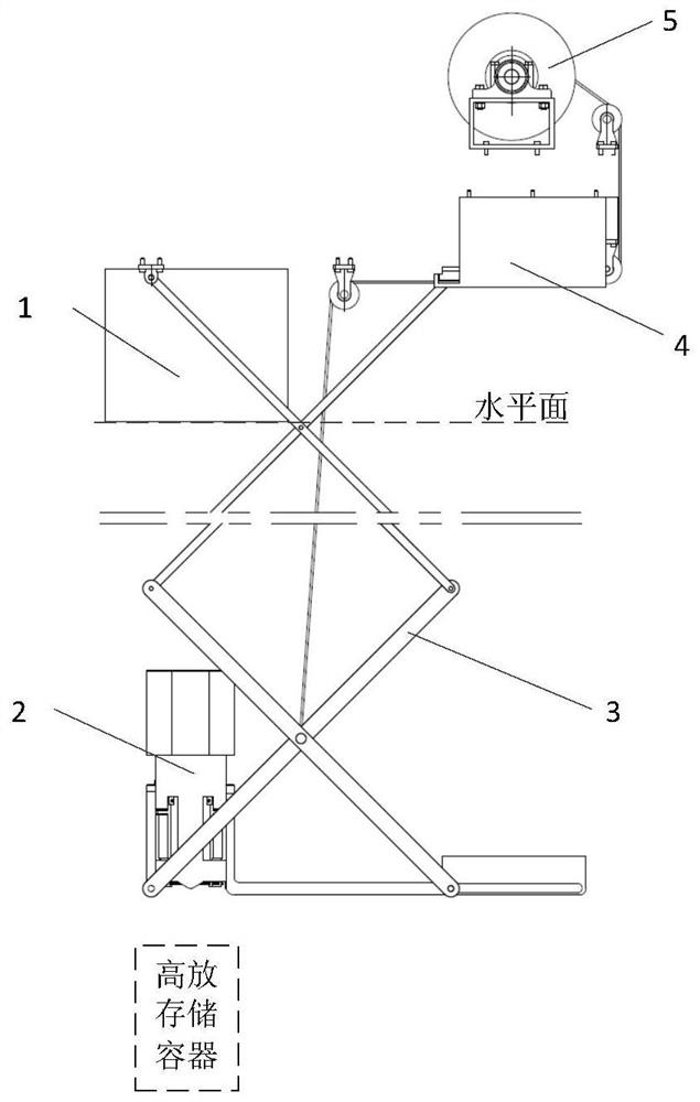
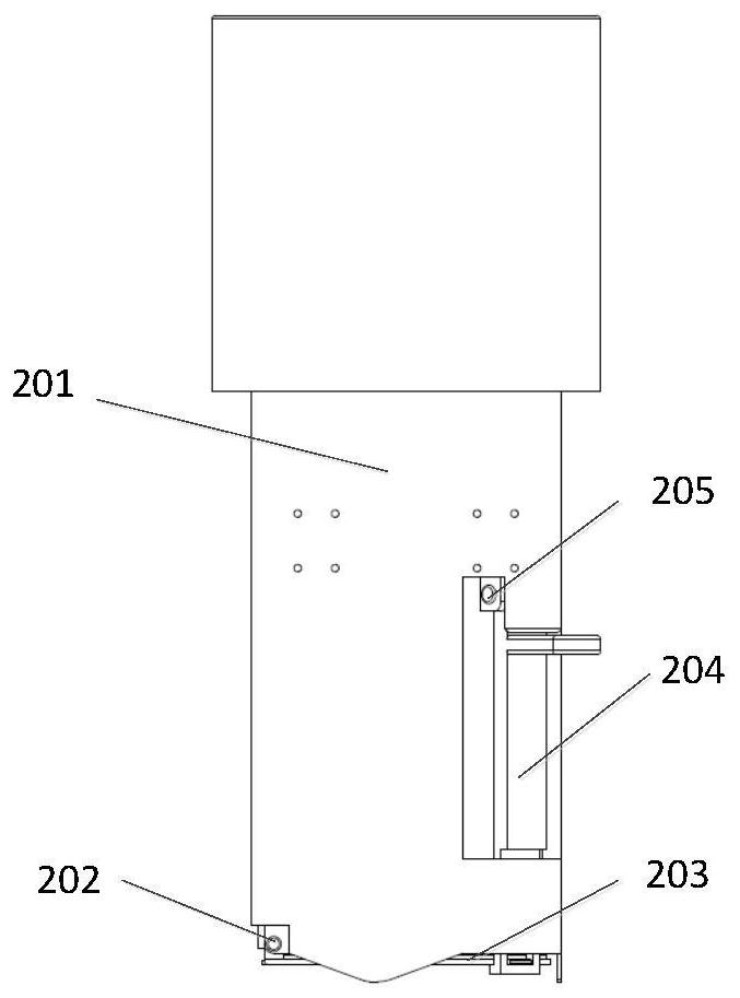
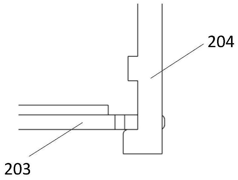
[0048] Such as Figure 1-Figure 8 As shown, the liftable temporary storage container assembly for dismantling the nuclear reactor detector assembly includes a telescopic mechanism 3, a temporary storage container 2 and a hoisting mechanism 5. The top of the telescopic mechanism 3 is fixed, and the telescopic mechanism 3 is stretched through the hoisting mechanism 5. , the temporary storage container 2 is installed at the bottom of the telescopic mechanism 3, the temporary storage container 2 includes a cylinder 201, the top and bottom of the cylinder 201 are open structures, and the bottom opening of the cylinder 201 fits An opening and closing door 203 is provided, and the temporary storage container 2 is arranged above the high storage container, and can be lowered into the high storage container under the action of the telescopic mechanism 3; the opening and closing door 203 is connected with the first torsion spring 202 The bottom of the cylinder 201 is connected, and the ...
Embodiment 2
[0057] Such as Figure 1-Figure 8 As shown, this embodiment is based on Embodiment 1, and further includes a shielding cylinder 1 arranged above the temporary storage container 2, the temporary storage container 2 is submerged below the water surface, and the bottom of the shielding cylinder 1 is in contact with or submerged in the water surface Below the water surface, the temporary storage container 2 can be embedded in the shielding cylinder 1, and the inner cavity size of the shielding cylinder 1 matches the outer dimension of the temporary storage container 2. When the temporary storage container receives the dismantled detector assembly, it For radiation shielding, the top and bottom of the shielding cylinder 1 are both open structures; the shielding cylinder 1 is made of lead plate, and the temporary storage container 2 is made of tungsten alloy.
[0058] In this embodiment, the full stroke double radiation shielding is performed on the disassembled detector assembly: ...
Embodiment 3
[0061] Such as Figure 1-Figure 8 Shown, this embodiment is based on embodiment 1 or embodiment 2
[0062] Also includes a guide rail assembly 4, one end of the upper X-shaped telescopic assembly is fixed, and the other end is installed on the guide rail assembly 4; the guide rail assembly 4 includes a slider 401, a guide rail 402 and a base 403;
[0063] The slider 401 is installed in the guide rail 402, the slider 401 is connected with the telescopic mechanism, the guide rail 402 is installed on the base 403, and both ends of the base 403 are provided with mechanical stoppers to limit the slider 401 motion stroke.
[0064] In this embodiment, double anti-falling measures are used to ensure high safety performance: two sets of flexible parts are used for transmission, reducing the risk of falling due to transmission damage; one end of the telescopic mechanism 3 is connected to the guide rail assembly 4, and the guide rail assembly 4 has a mechanical limit Function, when the...
PUM
 Abstract
Description
Claims
Application Information
 - R&D
- Intellectual Property
- Life Sciences
- Materials
- Tech Scout
- Unparalleled Data Quality
- Higher Quality Content
- 60% Fewer Hallucinations
Browse by: Latest US Patents, China's latest patents, Technical Efficacy Thesaurus, Application Domain, Technology Topic, Popular Technical Reports.
© 2025 PatSnap. All rights reserved.Legal|Privacy policy|Modern Slavery Act Transparency Statement|Sitemap|About US| Contact US: help@patsnap.com


