Substrate bearing device and detection device

A technology for carrying devices and substrates, which is used in semiconductor/solid-state device testing/measurement, electrical components, semiconductor/solid-state device manufacturing, etc., which can solve the problem of poor repeatability, difficulty in locking the manipulator, and difficulty in ensuring that the manipulator can reach the exact same measurement station. And other issues

Pending Publication Date: 2020-10-23
SHANGHAI PRECISION MEASUREMENT SEMICON TECH INC
View PDF7 Cites 1 Cited by
  • Summary
  • Abstract
  • Description
  • Claims
  • Application Information

AI Technical Summary

Problems solved by technology

On the one hand, it is difficult for the manipulator to be stably locked in a specific posture. If it shakes, it will affect the measurement accuracy. On the other hand, it is difficult for the manipulator to ensure that it can reach the exact same measurement position every time, and the repeatability is poor.

Method used


Image

  • Substrate bearing device and detection device
  • Substrate bearing device and detection device
  • Substrate bearing device and detection device

Examples


Embodiment 1

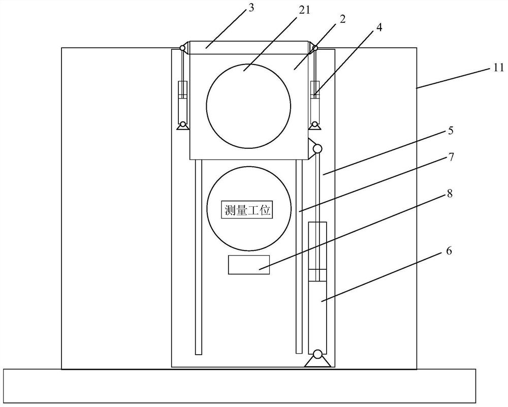
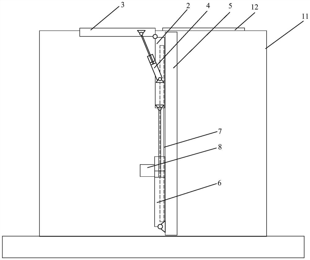
[0061] figure 1 and figure 2 It is a schematic diagram of the internal structure of the substrate carrying device under the first viewing angle and the second viewing angle when the carrier is in a horizontal posture, as shown in Figure 1-Figure 2 As shown, the substrate carrying device includes a cavity 11 , a mounting plate 2 and a stage 3 . Wherein, an opening is provided on the top of the cavity 11 , the mounting plate 2 is disposed inside the cavity 11 , the stage 3 is used to clamp the substrate 100 , and the stage 3 is rotatably matched with the mounting plate 2 . The platform 3 can be selectively turned over to a horizontal position and at least partly protrudes from the cavity 11 from the opening of the cavity 11 , or turned over to a vertical position and completely accommodated in the cavity 11 .

[0062] When the substrate carrying device of this embodiment is in use, the vacant stage 3 is turned over to a horizontal posture first, and at this time, the stage 3...

Embodiment 2

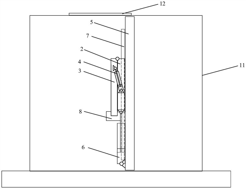
[0080] The overturning process of the stage 3 requires a certain space. If the position after the stage 3 rotates the substrate 100 to a vertical posture is the measurement station, then the measurement component cannot be set at a position closer to the measurement station. A measurement component is set near the station. In order to achieve measurement, the measurement component needs to move to other positions for avoidance before the stage 3 rotates. When the stage 3 moves to the measurement station with the substrate 100, the measurement component returns to the measurement station. Measurement near the position, that is, every time a substrate is measured, the measurement component needs to perform avoidance and return movements, which will not only lead to low measurement efficiency, but also have an adverse effect on the focusing function of the measurement component if the measurement component is an optical measurement component. In addition, in actual production, the...


PUM


Abstract

The invention relates to the technical field of substrate detection, and discloses a substrate bearing device and a detection device. The substrate bearing device comprises a cavity, a mounting plateand a carrying table, wherein an opening is formed in the top part of the cavity; the mounting plate is arranged in the cavity; the carrying table is used for clamping a substrate; the carrying tableis in running fit with the mounting plate; and the carrying table can be selectively overturned to a horizontal posture and at least partially protrudes out of the cavity from the opening, or overturned to a vertical posture and completely contained in the cavity. The substrate bearing device is simple in structure, can conveniently and accurately hand over the substrate to a manipulator, and canmeasure the vertical posture of the substrate. The detection device provided by the invention comprises the substrate bearing device, and can conveniently and accurately transfer the substrate to themanipulator through using the substrate bearing device.

Description

technical field [0001] The invention relates to the technical field of substrate detection, in particular to a substrate carrying device and a detection device. Background technique [0002] In order to form a target product based on substrate processing, it is necessary to obtain the surface topography information of the substrate in advance. Based on the surface topography information, the preset process is completed on the substrate, and the target product is finally obtained. [0003] Taking the substrate as a wafer as an example, in the wafer production or chip manufacturing process, the wafer often has morphology changes. For example, in processes such as coating, etching, chemical mechanical polishing or heat treatment, the surface morphology of the wafer may be If such a change in shape is not known in processes such as lithography, adaptive adjustments cannot be made according to the change in shape, and the change in surface shape of the wafer will not be conduciv...

Claims


Application Information

Patent Timeline
Patent Type & Authority Applications(China)
IPC IPC(8): H01L21/687H01L21/66
CPCH01L21/68764H01L22/12
Inventor 陈梦来
Owner SHANGHAI PRECISION MEASUREMENT SEMICON TECH INC
Why Eureka
Try Eureka