Fog specification device, fog specification method and fog specification program

A technology for determining a device and a determining part, which is applied in the field of determining the concentration of fog and can solve problems such as reduction in brightness

Active Publication Date: 2020-10-23
MITSUBISHI ELECTRIC CORP
View PDF5 Cites 0 Cited by
  • Summary
  • Abstract
  • Description
  • Claims
  • Application Information

AI Technical Summary

Problems solved by technology

Specifically, when fog is not generated, the brightness of the area where the irradiation light is not irradiated decreases.

Method used


Image

  • Fog specification device, fog specification method and fog specification program
  • Fog specification device, fog specification method and fog specification program
  • Fog specification device, fog specification method and fog specification program

Examples


Embodiment approach 1

[0030] ***Description of structure***

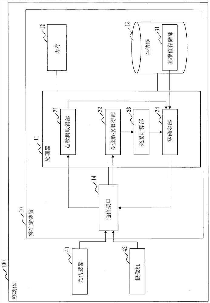
[0031] refer to figure 1 The configuration of the fog specifying device 10 according to Embodiment 1 will be described.

[0032] The fog specifying device 10 is a computer such as an ECU (Electronic Control Unit: Electronic Control Unit) mounted on the mobile body 100 .

[0033] In Embodiment 1, the mobile body 100 is a vehicle. However, the mobile body 100 is not limited to vehicles, and may be other types such as ships and airplanes. The fog identification device 10 may be installed integrally or inseparably with the mobile body 100 or other structural elements shown in the figure, or may be installed detachably or detachably.

[0034] The fog identification device 10 has hardware such as a processor 11 , a memory 12 , a storage 13 , and a communication interface 14 . The processor 11 is connected to other hardware via signal lines, and controls these other hardware.

[0035] The processor 11 is an IC (Integrated Circuit) that per...

Deformed example 1

[0067] In Embodiment 1, the mist specifying unit 24 determines whether or not mist having a certain density or higher is generated. However, the mist specifying unit 24 may specify which density of mist is present in a plurality of stages in the state around the moving object 100 .

[0068] In this case, if Image 6 As shown, in the reference value storage unit 31 , reference values ​​are stored for each distance with respect to the density of each mist. exist Image 6 , the reference value for each distance is stored for the fog with a visual range of 15 m, the fog with a visual range of 30 m, and the fog with a visual range of 50 m. Further, the fog specifying unit 24 compares the reference value corresponding to the distance from the optical sensor 41 to the reflection point and the smoothness of the luminance for each concentration of the fog, and specifies the density of the fog.

[0069] Specifically, when the luminance is smoother than the reference value for the fog...

Deformed example 2

[0072] In Embodiment 1, each functional component is realized by software. However, as Modification 2, each functional constituent element may also be realized by hardware. Regarding Modification 2, points different from Embodiment 1 will be described.

[0073] refer to Figure 7 The configuration of the fog specifying device 10 according to Modification 2 will be described.

[0074] When each functional component is realized by hardware, the fog identification device 10 has an electronic circuit 15 instead of the processor 11 , the memory 12 , and the storage 13 . The electronic circuit 15 is a dedicated circuit that realizes the functions of each functional structural element, the memory 12 and the memory 13 .

[0075] As the electronic circuit 15, it is assumed that it is a single circuit, a composite circuit, a programmed processor, a parallel programmed processor, a logic IC, a GA (Gate Array: gate array), an ASIC (Application Specific Integrated Circuit: an integrated...


PUM


Abstract

According to the present invention, a point data acquisition part (21) acquires point data that indicates a reflection point and has been obtained by a light sensor (41) that receives reflected lightthat is the result of a radiated light beam being reflected at the reflection point. An image data acquisition part (22) acquires image data for the surroundings of the reflection point indicated by the point data. A brightness calculation part (23) calculates the smoothness of the brightness of the image data. A fog specification part (24) specifies the thickness of fog from the smoothness of thebrightness and from the distance, as specified from the point data, from the light sensor (41) to the reflection point.

Description

technical field [0001] The present invention relates to techniques for determining the concentration of fog. Background technique [0002] Patent Document 1 describes a technique for determining whether or not fog is generated around a vehicle. [0003] In Patent Document 1, when headlights emit light, it is determined whether or not fog has occurred based on a difference in brightness of an area not irradiated with light in an image obtained by capturing the front of the vehicle. Specifically, when fog is not generated, the brightness of the area where the irradiation light is not irradiated decreases. On the other hand, when fog is generated, the irradiated light is reflected by the particles of the fog, so the brightness gradually increases from the inside to the outside of the image. In Patent Document 1, this characteristic is used to determine whether fog is generated. [0004] prior art literature [0005] patent documents [0006] Patent Document 1: Japanese Pat...

Claims


Application Information

Patent Timeline
Patent Type & Authority Applications(China)
IPC IPC(8): G01W1/00G01S17/95G06V10/60
CPCG01S17/95G01W1/02G01S17/89G01S17/931G01S7/4802Y02A90/10G06V20/58G06V10/60G01S17/86
Inventor 广井公彦
Owner MITSUBISHI ELECTRIC CORP
Why Eureka
Try Eureka