Exhaust gas post-treatment method and exhaust gas post-treatment system for internal combustion engine

A technology for after-treatment of exhaust gas and internal combustion engine, which is applied in the direction of electronic control of exhaust gas treatment device, diagnostic device of exhaust gas treatment device, exhaust gas treatment, etc., can solve the problems of increased water injection cost, high water consumption, damage, etc. To achieve the effect of reducing exhaust gas temperature

Active Publication Date: 2020-07-24
VOLKSWAGEN AG
View PDF13 Cites 0 Cited by
  • Summary
  • Abstract
  • Description
  • Claims
  • Application Information

AI Technical Summary

Problems solved by technology

On the one hand an additional injector is required to introduce the water
In addition, the water consumption is correspondingly higher at load conditions with a high full load specific gravity, which can lead to the need for the driver to refill water at each petrol station similar to refueling
Demineralized water (soft water) is used to avoid damage to the internal combustion engine, which increases the cost of spraying water

Method used


Image

  • Exhaust gas post-treatment method and exhaust gas post-treatment system for internal combustion engine
  • Exhaust gas post-treatment method and exhaust gas post-treatment system for internal combustion engine
  • Exhaust gas post-treatment method and exhaust gas post-treatment system for internal combustion engine

Examples


Embodiment Construction

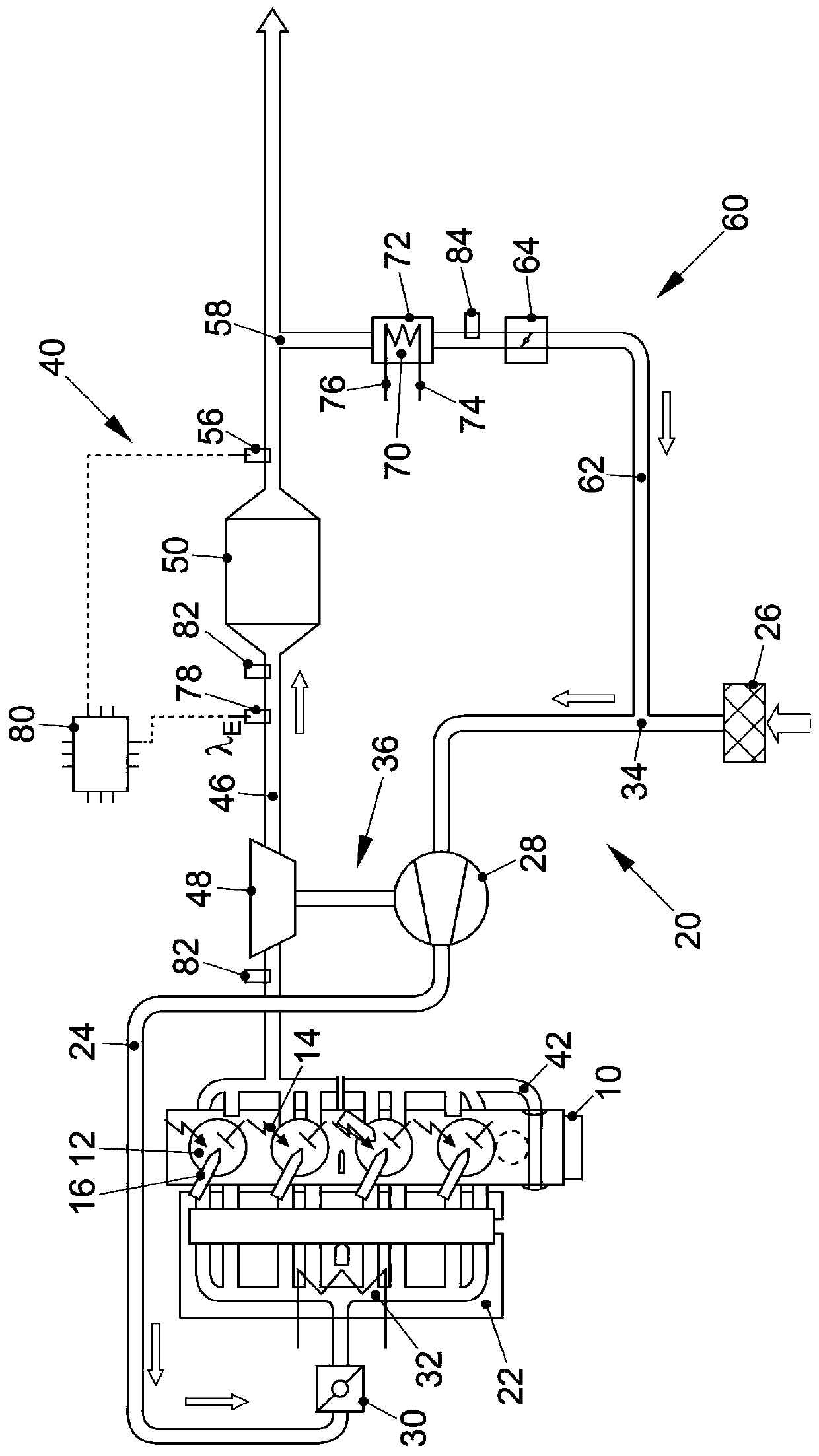
[0037] figure 1 A schematic diagram of an internal combustion engine 10 with an intake system 20 and an exhaust system 40 is shown. Internal combustion engine 10 is designed as a direct-injection gasoline engine and has a plurality of combustion chambers 12 . A fuel injector 16 for injecting fuel into the respective combustion chamber 12 and a spark plug 14 for igniting the fuel-air mixture are respectively arranged at the combustion chambers 12 . The combustion chamber 12 is delimited by a piston 18 which is arranged linearly displaceable in a cylinder bore of the internal combustion engine 10 . The piston 18 is connected to the crankshaft of the internal combustion engine 10 through a connecting rod, and the crankshaft transmits the power of the internal combustion engine 10 to an output shaft that can be connected to the transmission. Internal combustion engine 10 is connected via its intake port 22 to an air supply system 20 and via its exhaust port 42 to an exhaust syst...


PUM


Abstract

The invention relates to a method for processing exhaust gas of an internal combustion engine (10) with at least one combustion chamber (12). The air inlet (22) of the internal combustion engine is connected to a gas feeding system (20); and the air outlet of the internal combustion engine is connected with an exhaust device (40) of the internal combustion engine. Each combustion chamber is provided with at least one ignition device, which is used to ignite a stoichiometric combustion air mixture in the combustion chamber. The exhaust device is provided with an exhaust channel (46), and at least one exhaust gas post-treatment member is arranged in the exhaust channel. The exhaust device is connected to the gas feeding system of the internal combustion engine through an exhaust gas recirculation system (60), and an exhaust gas recirculation cooler (70) is arranged in the exhaust gas recirculation system. The method comprises the following steps: burning the stoichiometric combustion airmixture (lambda=1) to operate the internal combustion engine; purifying the exhaust gas of the internal combustion engine by an exhaust gas post-treatment component; determining the operation point of the internal combustion engine; and adjusting the exhaust gas recirculation rate at a constant load point of the internal combustion engine so as to change the temperature of the exhaust gas.

Description

technical field [0001] The invention relates to a method for aftertreatment of exhaust gases of an internal combustion engine and an exhaust aftertreatment system for carrying out such a method. The exhaust port is connected to the exhaust system of the internal combustion engine, wherein at least one ignition device is arranged at each combustion chamber in order to ignite the stoichiometric combustion air mixture in said combustion chamber, wherein the exhaust system has an exhaust duct in which at least one exhaust gas aftertreatment component is arranged and wherein the exhaust system is connected to the intake system via an exhaust gas recirculation system in which exhaust gas is arranged recirculation cooler. Background technique [0002] Current and future increasingly stringent emission regulations place high demands on the raw or untreated emissions of engines and the exhaust gas aftertreatment of internal combustion engines. In this case, in order to comply with ...

Claims


Application Information

Patent Timeline
Patent Type & Authority Applications(China)
IPC IPC(8): F02D41/00F02D41/02F02P5/15F02D21/08F02M26/05F02M26/06F02M26/07F02M26/15F01N13/00F02D41/14
CPCF02D41/0077F02D41/021F02P5/1516F02D21/08F02M26/05F02M26/06F02M26/07F02M26/15F01N13/009F02D41/1475F01N3/101F01N9/00F01N11/00F01N2900/1602F01N2430/08F01N2240/02F01N3/02F01N2560/025F02M26/22F02M26/50F02M26/35F02D2041/0265F02D41/1446F02D41/0007F02D41/0055F02B2075/125F02D35/02F02D2041/0067F02D37/02F02D35/024Y02T10/12Y02T10/40
Inventor A.格罗特C.马斯G.布洛克K.布兰德斯
Owner VOLKSWAGEN AG
Why Eureka
Try Eureka