Scissor-type lifting mold-replacing trolley and full-automatic mold-replacing storage system thereof

A technology of mold trolley and lifting table, which is applied in the field of scissor-type lifting mold changing trolley and its automatic mold replacement storage system, which can solve the problems of increased labor intensity, large safety hazards, mold damage, etc.

Pending Publication Date: 2020-10-27
NINGBO YIJIE PRECISION MACHINERY CO LTD
View PDF0 Cites 0 Cited by
  • Summary
  • Abstract
  • Description
  • Claims
  • Application Information

AI Technical Summary

Problems solved by technology

[0004] Therefore, how to quickly transfer the mold to complete the mold change has become a technical problem. At present, the mold change operation mainly uses trolley transfer or crane, forklift and other lifting equipment to change the mold. Using a trolley to transfer the mold requires manual removal of the mold. Transport to the machine table, mold rack, and trolley, and the operator who uses the lifting equipment to change the mold needs to have a good operating level, otherwise it is easy to cause damage to the mold. It requires a high degree of participation of the operator, and the process of moving a large number of molds is time-consuming and laborious, which brings a lot of inconvenience to the staff, increases the labor intensity of the work, inefficiency, and the risk of potential safety hazards over time is also greater

Method used


Image

  • Scissor-type lifting mold-replacing trolley and full-automatic mold-replacing storage system thereof
  • Scissor-type lifting mold-replacing trolley and full-automatic mold-replacing storage system thereof
  • Scissor-type lifting mold-replacing trolley and full-automatic mold-replacing storage system thereof

Examples


Embodiment 1

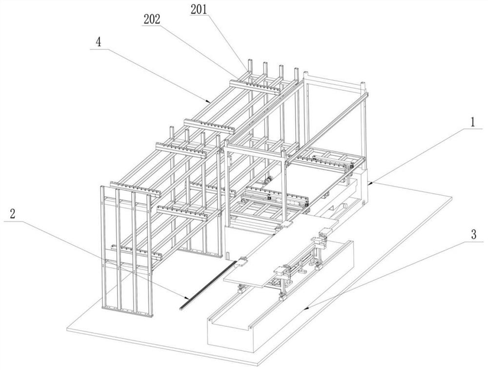
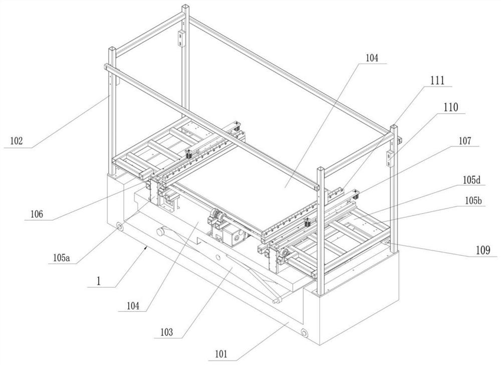
[0052] Such as figure 1 and figure 2As shown, a scissor-type lifting mold changing trolley includes a frame body 1, which is slidably mounted on a slide rail 2, and the two ends of the slide rail 2 extend to the machine platform 3 and multiple Layer mold frame 4, vehicle frame body 1 comprises: base 101, door frame 102, scissors arm 103, lifting platform 104, support frame 105 and two-way push-pull mechanism 107, door frame 102 is installed on the upper edge place of base 101, scissors arm 103 One end of which is fixed on the base 101, and the lifting platform 104 is installed on the end of the scissor arm 103 away from the base 101, so that the scissor arm 103 is clamped between the lifting platform 104 and the base 101, and the support frame 105 is installed on the lifting platform 104 On the end face, guide rails 106 are installed on both sides of the upper end face of the support frame 105 relative to its center line, and the two-way push-pull mechanism 107 is connected ...

Embodiment 2

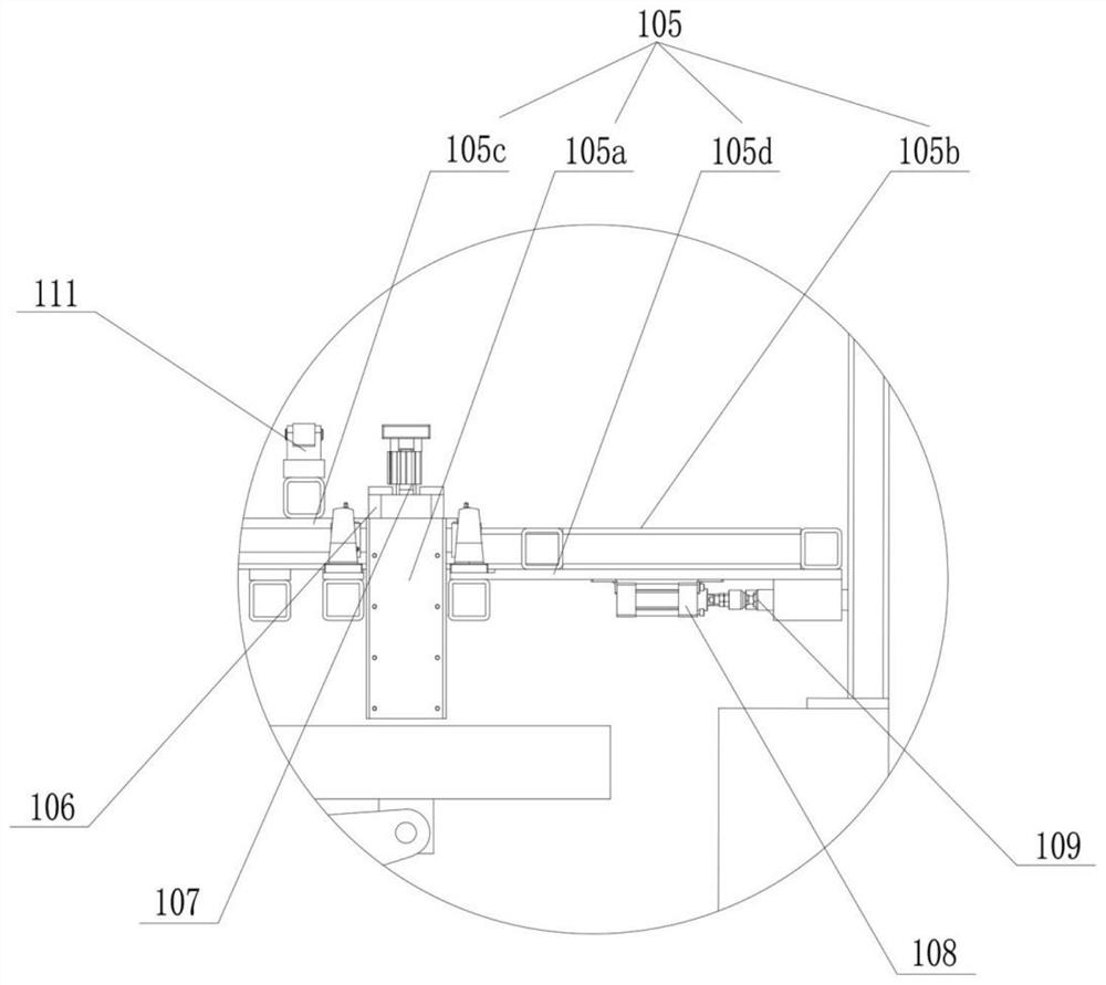
[0060] Such as figure 2 and image 3 As shown, in this embodiment, on the basis of the above-mentioned embodiment 1, one of the optimized designs is made. The support plate 105d is fixed below the two ends of the bracket 105b close to the door frame 102, and a plurality of second plates are installed on the support plate 105d. The cylinders 108 and the piston rods of each second cylinder 108 are connected with positioning pins 109 .

[0061] Such as figure 2 As shown, furthermore, the door frame 102 is provided with positioning seats 110 equal in number to the positioning pins 109 and corresponding one-to-one, and can abut against the positioning seats 110 when the positioning pins 109 are stretched out.

[0062] In this embodiment, the setting of the second cylinder 108, the positioning pin 109 and the positioning seat 110 can prevent the lifting platform 104 from falling, specifically, when the scissor arm 103 lifts the lifting platform 104, in order to ensure that the l...

Embodiment 3

[0064] Such as figure 1 and figure 2 As shown, in this embodiment, one of the optimized designs is made on the basis of the above-mentioned embodiment 1. The top plate 105c is provided with a first auxiliary wheel set 111 which is equal in number to the guide rail 106 and arranged along the length direction of the guide rail 106. There are second auxiliary wheel sets 201 equal in number to the first auxiliary wheel sets 111 on each storage position of the mold frame 4 .

[0065] Such as figure 1 As shown, further, the end of the second auxiliary wheel set 201 facing away from the first auxiliary wheel set 111 is provided with a limiting plate 202 to prevent dislocation of the mold.

[0066] In this embodiment, when the two-way push-pull mechanism 107 controls the movement of the mould, both the first auxiliary wheel set 111 and the second auxiliary wheel set 201 can change the sliding friction on the mold into rolling friction, thereby avoiding the occurrence of lowering of...


PUM


Abstract

The invention relates to a scissor-type lifting mold-replacing trolley. The scissor-type lifting mold-replacing trolley comprises a trolley frame body. The trolley frame body can be arranged on a sliding rail in a sliding mode. The two ends of the sliding rail respectively extend to a machine platform and a multi-layer mold frame. The trolley frame body comprises a base, a door frame, a lifting platform, a supporting frame, and a two-way pull-and-push mechanism. The door frame is arranged on a scissors arm on the upper edge of the base, and one end of the door frame is fixed to the base. The lifting platform is arranged on one end, away from the base, of the scissors arm, and makes the scissors arm to be clamped between the lifting platform and the base. The supporting frame is arranged onthe upper end face of the lifting platform, and two sides, relative to the center line of the supporting frame, of the upper end face of the supporting frame are provided with two guiding rails. Thetwo-way pull-and-push mechanism is connected with the guiding rails, and can be moved along the direction of the guiding rails. According to the technical scheme, the mold-replacing trolley is low inmanual participation, small in manual work intensity, high in safety; at the same time the mold-replacing trolley can effectively save the working time and improve the efficiency of the mold-replacingwork while conducting the mold-replacing work.

Description

technical field [0001] The invention relates to the field of mold equipment manufacturing, and more specifically relates to a scissor-type lifting mold changing trolley and a fully automatic mold changing storage system. Background technique [0002] Mold is a variety of molds and tools to obtain the required products by injection molding, blow molding, extrusion, die-casting or forging, smelting, stamping and other methods. It is one of the core parts of industrial production. Different molds are composed of different parts. Composition, the mold mainly realizes the processing of the shape of the article through the change of the physical state of the formed material. Known as the "Mother of Industry". [0003] In industrial production, different molds need to be used, and frequent mold change operations are required. The used molds need to be transferred from the machine table to the mold rack for storage, and then the mold to be used is removed from the mold rack for tra...

Claims


Application Information

Patent Timeline
IPC IPC(8): B65G1/04B66F7/06
CPCB65G1/0435B66F7/065
Inventor 王德臣
Owner NINGBO YIJIE PRECISION MACHINERY CO LTD
Why Eureka
Try Eureka