Water electrolysis gas production device and method

A technology for electrolyzing water and gas devices, which is applied in the electrolysis process, electrolysis components, cells, etc., and can solve problems such as increased pressure difference of the diaphragm, high pressure in the cathode electrolysis chamber, and rupture of the diaphragm.

Active Publication Date: 2020-10-27
宁波中科氢易膜科技有限公司
View PDF12 Cites 2 Cited by
  • Summary
  • Abstract
  • Description
  • Claims
  • Application Information

AI Technical Summary

Problems solved by technology

[0010] Patent document CN111005029A discloses: the use of a common anode and symmetrical double cathode design realizes the self-balancing pressure of electrolyzed water for gas production, without the need for an external pressure balance pump, which can greatly improve the stability and efficiency of high-pressure electrolyzed water for gas production. Channel design, that is, two cathodes share one liquid inlet channel and one liquid discharge channel, and the anode uses another liquid inlet channel and liquid discharge channel. The total amount of gas generated on the two cathodes during electrolysis is twice that of the gas generated by the anode. Therefore, in the cathode drainage channel, it is very easy to fail to discharge due to excessive gas production, resulting in excessive pressure in the cathode electrolysis chamber, which increases the pressure difference on both sides of the diaphragm, and eventually causes the diaphragm to rupture.

Method used


Image

  • Water electrolysis gas production device and method
  • Water electrolysis gas production device and method
  • Water electrolysis gas production device and method

Examples


no. 1 example

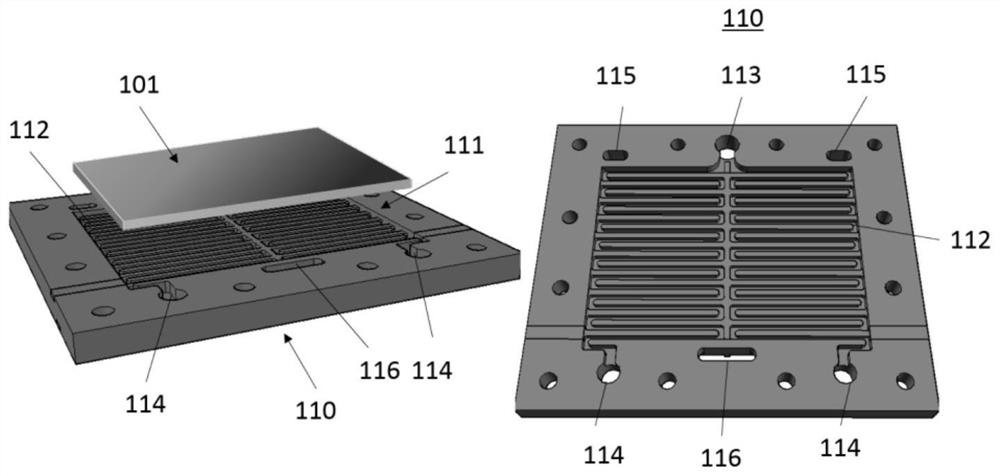
[0107] like image 3 , 4 and Image 6 As shown, the electrolyzed water gas generating device 10 provided in this embodiment includes a plurality of electrolyzed water gas generating units 100 connected in series. Specifically, it includes a first electrolyzed water gas generating unit 100a, a second electrolyzed water gas generating unit 100c, and a middle electrolyzed water gas generating unit 100b.

[0108] like Figure 7 As shown, two adjacent electrolyzed water gas generating units 100 connected in series are connected to the anode plate 110 through their respective cathode plates 120 , and are integrally formed into a bipolar plate 105 . That is, one side of the bipolar plate 105 has the same structure as the cathode plate 120 , and the other side has the same structure as the anode plate 110 . This arrangement is convenient for assembling a plurality of electrolyzed water gas generating units 100 into one body. The structure of the device obtained after assembly is ...

no. 2 example

[0120] This embodiment is basically the same as the first embodiment, the difference is only in the location of the electrolyte inlet pipe and outlet pipe, and the structure of the first electrolyzed water gas generating unit 100a and the second electrolyzed water gas generating unit 100c.

[0121] like Figure 9 and Figure 10 As shown, in the device provided in this embodiment, two catholyte water outlet pipes 106, one catholyte water inlet pipe 107, two anolyte water inlet pipes 108, and one anolyte water outlet pipe 109 are all arranged on a bipolar plate 105 on the peripheral wall, the bipolar plate 105 is named as the middle plate 150, and the structure of the middle plate 150 is as follows Figure 11 shown.

[0122] The anolyte outlet 113 , the anolyte inlet 114 , the first through hole 115 and the second through hole 116 are not provided on the anode plate 110 of the first electrolyzed water gas generating unit 100 a. The catholyte outlet 123 , the catholyte inlet 1...

no. 3 example

[0124] This embodiment is basically the same as the first embodiment, the difference is only in the location of the electrolyte inlet pipe and outlet pipe, and the structure of the first electrolyzed water gas generating unit 100a and the second electrolyzed water gas generating unit 100c.

[0125] like Figure 12 and Figure 13 As shown, in the device provided in this embodiment, two catholyte outlet pipes 106 and one anolyte outlet pipe 109 are arranged on the anode plate of the first electrolyzed water gas generating unit 100a, and the first electrolyzed water gas generating unit 100a The anode plate 110 is not provided with an anolyte inlet 114 and a second through hole 116 . Two anolyte water inlet pipes 108 and one catholyte water inlet pipe 107 are arranged on the cathode plate 120 of the second electrolyzed water gas production unit 100c, and the cathode plate 120 is not provided with the catholyte outlet 123 and the fourth through hole 126.

[0126] It should be no...


PUM


Abstract

The invention relates to the technical field of water electrolysis gas production, and provides a water electrolysis gas production device and method. The water electrolysis gas making device comprises a water electrolysis gas production unit or a combination of a plurality of water electrolysis gas production units, wherein each water electrolysis gas production unit comprises a mutually independent anode reaction chamber, two cathode reaction chambers, an anode connected with an external power supply and two cathodes connected with the same external power supply, the two cathodes are connected in parallel, the anode is positioned in the anode reaction chamber, and the two cathodes are respectively positioned in the two cathode reaction chambers. The water electrolysis gas production method comprises the step of producing gas by electrolyzing water by adopting the device. According to the device and the method, the pressure difference between the anode reaction chamber and the cathodereaction chamber is basically zero, and the stability of the gas production process is good. Under the condition that the pressure difference is basically zero, electrolysis gas production can be carried out under extremely high pressure so that high-pressure gas can be directly produced without additional pressurization in the later period, and the requirement of on-site high-pressure hydrogen production is met.

Description

technical field [0001] The invention relates to the technical field of gas production by electrolysis of water, in particular to a device and method for gas production by electrolysis of water. Background technique [0002] Extensive use of fossil energy has led to global climate and environmental problems. For this reason, countries have vigorously developed renewable energy, such as wind energy, solar energy, and tidal energy. However, new energy sources such as wind energy and solar energy have uncontrollable fluctuations, and direct grid-connected power generation will bring devastating damage to the grid. Converting renewable energy into chemical energy by electrolyzing water to produce hydrogen is a feasible energy storage method, and combining it with renewable energy can well solve the impact of renewable energy on the grid. [0003] The electrolytic water reaction occurs in an electrolyzer, and the electrolyzer is mainly composed of a cathode, an anode, and a diaph...

Claims


Application Information

Patent Timeline
Patent Type & Authority Applications(China)
IPC IPC(8): C25B1/04C25B1/10C25B9/06C25B9/08C25B9/18
CPCC25B1/04Y02E60/36
Inventor 刘太楷邓春明刘敏宋琛
Owner 宁波中科氢易膜科技有限公司
Why Eureka
Try Eureka