Metal pipe inner surface electrodeposition device and method

A technology of electrodeposition device and metal tube, which is applied in current conduction device, sealing device, electrolysis process, etc., can solve the problems of environmental pollution, affecting the efficiency of operation, and occupying a large area.

Pending Publication Date: 2020-10-27
SHENGLI OIL FIELD HIGHLAND GASOLINEEUM EQUIP
View PDF6 Cites 5 Cited by
  • Summary
  • Abstract
  • Description
  • Claims
  • Application Information

AI Technical Summary

Problems solved by technology

However, the operation continuity of the existing process equipment is poor, and various surface cleaning, activation and electrodeposition equipment are scattered and occupy a large area; This process requires multiple mobile transportation of metal pipes, installation and disassembly of tooling equipment, which not only af...

Method used


Image

  • Metal pipe inner surface electrodeposition device and method
  • Metal pipe inner surface electrodeposition device and method
  • Metal pipe inner surface electrodeposition device and method

Examples


Embodiment 1

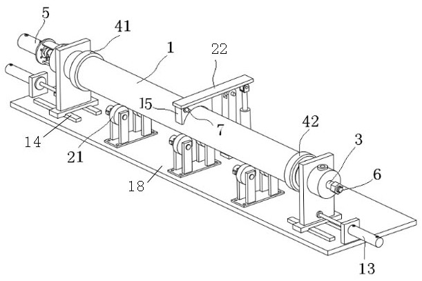
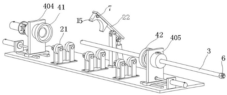
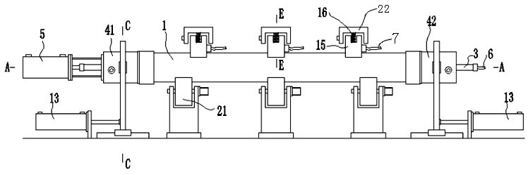
[0036] refer to Figure 1 to Figure 5 As shown, the electrodeposition device for the inner surface of a metal tube provided by the present invention includes a base 18 , an anode 3 , a carbon brush 15 , a compound joint, a reciprocating drive part 5 and a plurality of liquid storage tanks 8 .

[0037] The base 18 is provided with a plurality of support rollers 21 for horizontally supporting the metal pipe 1 and driving its circumferential rotation, and the base 18 is also provided with a motor for driving the support rollers 21 to rotate. The metal pipe 1 is horizontally supported and driven to rotate in the circumferential direction by the support roller 21 . Both ends of the base 18 are also respectively provided with a first slide 404 and a second slide 405, and the metal pipe 1 is located between the first slide 404 and the second slide 405; the middle part of the base 18 is also provided with a swing frame 22, An elastic member 16 for pressing the arc groove of the carbo...

Embodiment 2

[0045] As a preferred embodiment, it is basically the same as Embodiment 1, except that the front composite joint 41 and the rear composite joint 42 respectively include a front pipe section 401, a rear pipe section 402 and a rotary seal, and the rotary seal is arranged on the front pipe section 401 and the rear pipe section 401. Between the rear pipe sections 402, the liquid delivery port 403 is arranged in the rear pipe section 402 and communicates with the inner cavity of the rear pipe section 402. The front end of the front pipe section 401 is provided with an interface connected with the end of the metal pipe 1, and the rear pipe section 402 can slide up and down. It is arranged on the first sliding seat 404 , and similarly, the rear pipe section 402 of the rear composite joint 42 is arranged on the second sliding seat 405 so that it can slide up and down. The front end of the metal pipe 1 is fixedly connected and sealed to the interface of the front pipe section 401, and ...

Embodiment 3

[0056] Basically the same as Embodiment 2, the difference is that, as Figure 7 As shown, each liquid storage tank 8 includes a front liquid storage tank 81 and a rear liquid storage tank 82. The liquid delivery port is connected, and a filter part 9 for removing impurities is arranged between the front liquid storage tank and the rear liquid storage tank of the same liquid storage tank, and the filter part 9 for filtering out liquid impurities.

[0057] In addition, a filter member 9 for filtering out liquid impurities is provided between the delivery pipes at both ends in each liquid storage tank.

[0058] Wherein, the filter part 9 is an element for removing solid impurities in the liquid, such as a filter, a filter membrane, a filter screen, etc., which are conventional general-purpose products in industrial technology, and will not occupy space to repeat its detailed structure, working principle and other content.


PUM


Abstract

The invention discloses a metal pipe inner surface electrodeposition device, and relates to the technical field of metal pipe inner surface treatment. The device comprises a base, an anode, a carbon brush, composite joints, a reciprocating driving part and a plurality of liquid storage tanks. The base is provided with a plurality of supporting rollers used for horizontally supporting a metal pipeand driving the metal pipe to rotate in the circumferential direction, and two ends of the base are respectively provided with a first sliding seat and a second sliding seat; a swing frame is furtherarranged in the middle of the base; two ends of the metal pipe are respectively provided with the composite joints; and a deoiling cleaning liquid storage tank, a deionized water storage tank and a surface activating liquid storage tank are respectively connected with liquid conveying ports of the composite joints arranged at the front end and the rear end of the metal pipe through different conveying pipes, the processes of deoiling, washing, acidifying, activating, electrodepositing and the like on the inner wall of the metal pipe are automatically completed under the control of a liquid flow switch valve, the work of replacing and resealing the composite joints is not needed during the process, and the work efficiency is improved, and the scattering phenomenon of a working site and treatment liquid is reduced.

Description

technical field [0001] The invention relates to the technical field of metal tube inner surface treatment, in particular to an electrodeposition device and method for the inner surface of a metal tube. Background technique [0002] In the process of oil production, metal pipes such as oil pump barrels and oil pipes are used as equipment for transporting well fluid from downhole to the surface. They work under the conditions of corrosion, high temperature and sucker rod friction for a long time, which are prone to corrosion and wear problems, resulting in equipment damage. damage. At present, the industry adopts surface electroplating chromium plating, chemical nickel phosphorus plating and other processes to improve the corrosion resistance and wear resistance of metal pipes. However, the pretreatment process is complicated and the waste water generated pollutes the environment, which is a restrictive promotion process. Be eliminated. [0003] Electrodeposition technology,...

Claims


Application Information

Patent Timeline
IPC IPC(8): C25D7/04C25D5/02C25D21/12C25D17/00C25D17/06C25D21/06C25D21/08C25D19/00
CPCC25D7/04C25D5/02C25D21/12C25D17/004C25D17/007C25D17/06C25D21/06C25D21/08
Inventor 潜凌朱新忠王群章李江雪
Owner SHENGLI OIL FIELD HIGHLAND GASOLINEEUM EQUIP
Why Eureka
Try Eureka