In-hole air bag expansion pressurization and vacuum-electroosmosis composite drainage precipitation system and method

An electroosmotic dewatering and internal airbag technology, which is applied in the fields of foundation pit engineering, geological engineering and geotechnical engineering, can solve the problems of easy flow interruption, low dewatering and water output efficiency of vacuum tube wells, and high cost.

Inactive Publication Date: 2020-10-27
TONGJI UNIV
View PDF3 Cites 6 Cited by
  • Summary
  • Abstract
  • Description
  • Claims
  • Application Information

AI Technical Summary

Problems solved by technology

[0004] However, in high water content and low permeability soil layers, vacuum tube well dewatering efficiency is not high and is prone to cut-off. Although vacuum electroosmotic dewatering has high water output efficiency, it also costs a lot.

Method used


Image

  • In-hole air bag expansion pressurization and vacuum-electroosmosis composite drainage precipitation system and method
  • In-hole air bag expansion pressurization and vacuum-electroosmosis composite drainage precipitation system and method

Examples


Embodiment 1

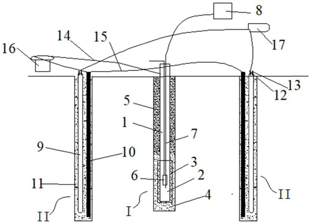
[0032] A kind of in-hole airbag expansion pressurization and vacuum-electroosmosis composite dewatering and dewatering system, such as Figure 1~2 Shown, comprise vacuum pumping mechanism 8 (preferably vacuum pump), DC power supply mechanism 16 (preferably DC generator), air compression mechanism 17 (preferably air compressor), a plurality of vacuum wells 1 and distribute in each Multiple lateral pressurization holes II around the vacuum dewatering well I;

[0033] The well tube of vacuum dehydration well 1 is connected with the negative electrode of DC power supply mechanism 16 by cathode connection electric wire 14, is provided with pumping mechanism and the vacuum exhaust pipe 7 that is connected with vacuum mechanism 8 in the well tube;

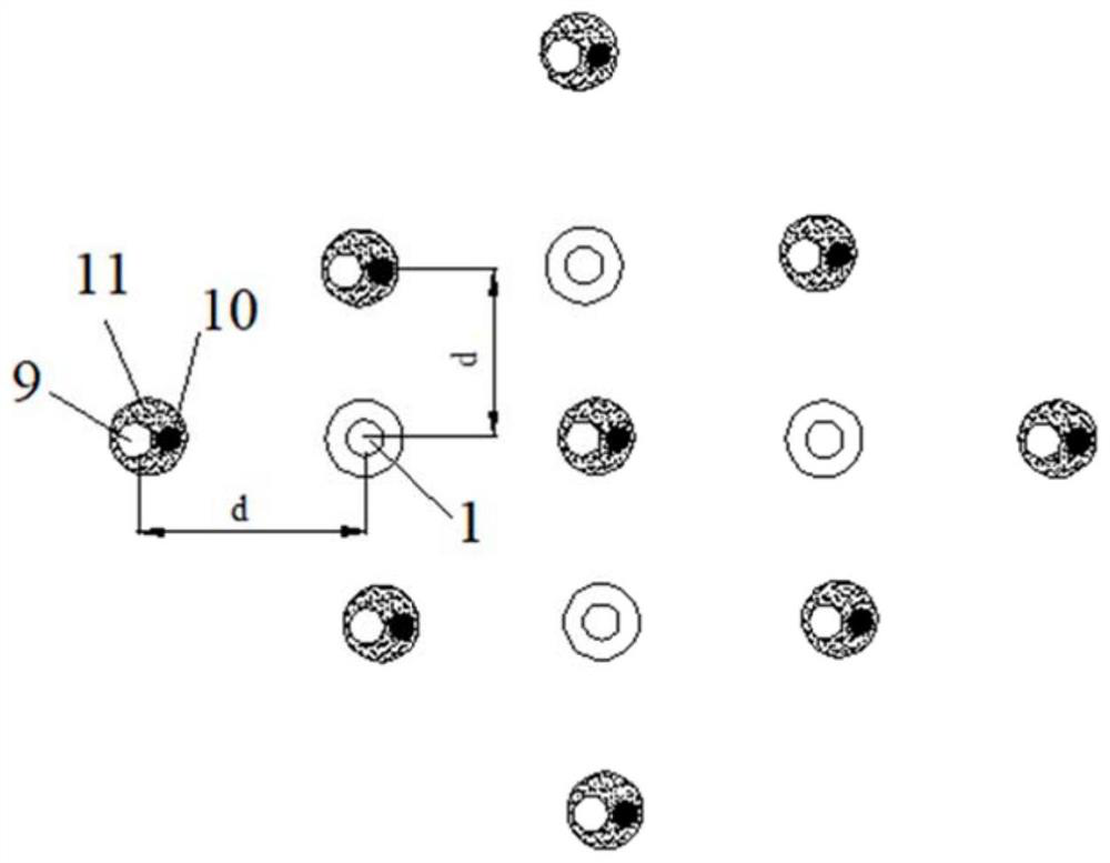
[0034] An anode metal post 10 and a flexible air bag 9 are placed in the lateral pressurization hole II, and the outside of the flexible air bag 9 and the anode metal post 10 is filled with a hole-filling mud 11, and the anode metal post ...

Embodiment 2

[0039] A kind of airbag expansion and pressurization and vacuum-electroosmosis compound dewatering dewatering method in a hole adopts the system of embodiment 1, the method includes vacuum tube well dewatering and vacuum intermittent electroosmotic dewatering successively, vacuum intermittent electroosmotic dewatering adopts continuous For vacuum tube well dewatering and intermittent electroosmotic dewatering, vacuum lateral pressurization dewatering is carried out in the interval of electroosmotic dewatering. Vacuum lateral pressurization dewatering refers to horizontal pressurization while vacuum tube well dewatering;

[0040] Vacuum well point dewatering is carried out by vacuum dewatering well I, which is used to discharge most of the free water under the action of vacuum suction to save electroosmotic dewatering time;

[0041]Vacuum intermittent electroosmotic dewatering is carried out by vacuum tube well dewatering by using vacuum dewatering well I, and using DC power sup...


PUM


Abstract

The invention relates to an in-hole air bag expansion pressurization and vacuum-electroosmosis composite drainage precipitation system and method. The system comprises a vacuumizing mechanism, a direct-current power supply mechanism, an air compression mechanism, a plurality of vacuum drainage wells and a plurality of transverse pressurizing holes distributed around each vacuum drainage well. Theprecipitation method comprises the following steps: (1) vacuum tube well drainage, wherein most of free water is drained under the action of vacuum suction force, and electroosmosis precipitation timeis saved; (2) vacuum electroosmosis precipitation, wherein part of pore water is drained under the action of vacuum suction force and electroosmosis force, and the water content of the soil body is further reduced; and (3) vacuum transverse pressurization precipitation, wherein a pressurization air bag is expanded squeeze the surrounding soil body, so that the pore ratio is rapidly reduced, the drainage precipitation speed is increased, and the soil body is reinforced. Compared with the prior art, by means of the effects of vacuum water absorption, air bag pressurization and electroosmosis, the risks of foundation pit excavation water gushing and pile foundation damage by soil movement in high-water-content and low-permeability soil layers are reduced, and rapid drainage precipitation ofmuddy soil is realized.

Description

technical field [0001] The invention belongs to the technical fields of geological engineering, geotechnical engineering and foundation pit engineering, and in particular relates to a system and method for inflating and pressurizing an airbag in a hole and vacuum-electroosmotic composite dewatering and dewatering. Background technique [0002] In the construction environment with high groundwater level, well point precipitation is often used to drain the water in the foundation soil, promote the consolidation of the soil, improve the strength of the foundation, and provide relatively dry construction conditions. However, the muddy powdery clay and the powdery clay layer have high water content and poor permeability. It is difficult to dewater and dewater by conventional methods, which may lead to high water content and large deformation of the soil. There may be a risk of water gushing during excavation of the foundation pit, resulting in soil movement. To damage the pile fo...

Claims


Application Information

Patent Timeline
Patent Type & Authority Applications(China)
IPC IPC(8): E02D3/00E02D3/10
CPCE02D3/00E02D3/10
Inventor 王建秀龙冠宏刘笑天何倩倩武昭薛睿徐娜
Owner TONGJI UNIV
Why Eureka
Try Eureka