Super-overloading high-speed rail bearing with spherical roller center ball

A spherical roller and ball placement technology, which is applied in the field of high-speed rail bearings, can solve the problems of increased axial bearing capacity of bearings, inability to change the mechanical nature of stress concentration, and easy skewing of rollers.

Pending Publication Date: 2020-10-27
孟萍
View PDF0 Cites 0 Cited by
  • Summary
  • Abstract
  • Description
  • Claims
  • Application Information

AI Technical Summary

Problems solved by technology

[0003] (1) Stress concentration: The stress concentration at the end of the tapered roller bearing roller is an irreversible congenital fatal defect, and its common main hazard is to cause raceway indentation and peeling;
[0004] (2) The rollers are easy to skew: The biggest congenital fatal flaw of tapered roller bearings is that the uneven force on the contact line of the rollers during the rotation can easily make the rollers skew, which directly leads to indentation, peeling, and retention of the ring raceway. The cracking of the frame or the cracking of the ribs often occurs in the wheel bearings of heavy-duty vehicles. At present, developed countries are adopting the method of increasing the roller convexity to reduce the stress concentration at the end of the roller, but it still cannot change the mechanical nature of the stress concentration. Nor can it fundamentally correct the defects of its innate mechanical structure;
[0009] A. The radius of the spherical roller track is restricted by the radius of the bearing. The radius of the spherical roller track must be smaller than the bearing radius, which directly causes the curvature of the spherical roller track to be too large, so that the actual application range of the spherical roller track is very narrow, and only the spherical surface can be used. There is a very narrow circle of spherical surface at the largest diameter, so the setting of the roller length is very short. Any method of increasing the roller length and roller contact angle will lead to the thrust spherical roller bearing effect, which directly leads to the radial spherical roller bearing The unnecessary increase of the axial bearing capacity and the decrease of the radial bearing capacity can cause a sharp increase in the frictional resistance and frictional heat of the bearing and a sharp decrease in the rated speed, so that the many advantages of the spherical roller bearing cannot be used in a wider range of fields. Great application value,
[0010] B. At present: spherical roller bearings manufactured in various countries have two rows of rollers, and the axis line of the two rows of rollers must form a certain angle with the vertical axis of the bearing (SKF Bearing Comprehensive Catalog P692 page), and cannot be symmetrical to The axis line of the bearing, therefore: its spherical roller misses the circle that can make the axis line of the spherical roller symmetrical to the axis line of the bearing, which can minimize the frictional resistance of the roller, minimize the frictional heat, and maximize the bearing capacity. Road range

Method used


Image

  • Super-overloading high-speed rail bearing with spherical roller center ball
  • Super-overloading high-speed rail bearing with spherical roller center ball
  • Super-overloading high-speed rail bearing with spherical roller center ball

Examples


Embodiment 1

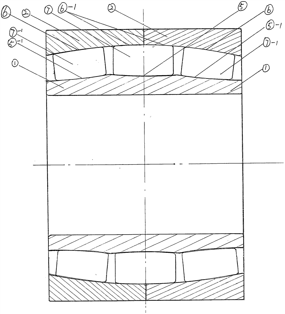
[0049] Such as figure 1 The shown super heavy-duty high-speed rail bearing with spherical roller centered balls includes an inner ring 1, two double-half outer rings 2, one ring of symmetrical spherical rollers 7 and two rings of asymmetrical spherical rollers 7 -1, the inner circumferences of the two double-half outer rings 2 are each provided with a spherical roller track 6. After the two double-half outer rings 2 are concentrically combined, their inner circumferences form a shared spherical roller track 6-1. The radius of curvature of the spherical roller track 6-1 is larger than the radius of the circumferential track of the bearing roller, so that the axial section of the shared spherical roller track 6-1 has an elliptical structure,

[0050] The inner ring 1 is provided with a central spherical roller track 5 in the middle of the axial distance of the outer circumference at the angle line perpendicular to the bearing axis line, and a symmetrical spherical roller 7 is ar...

Embodiment 2

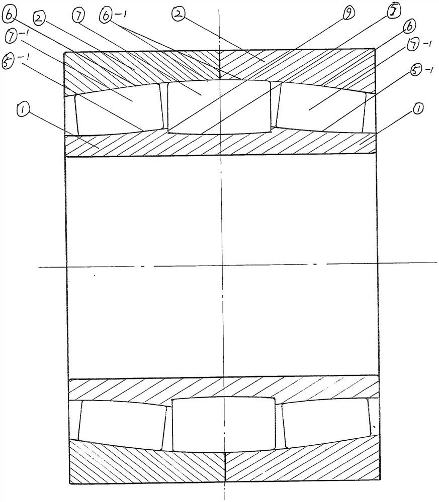
[0052] Such as figure 2 The shown super heavy-duty high-speed rail bearing with spherical roller centered balls includes an inner ring 1, two double-half outer rings 2, one ring of symmetrical spherical rollers 7 and two rings of asymmetrical spherical rollers 7 -1, the inner circumferences of the two double-half outer rings 2 are each provided with a spherical roller track 6. After the two double-half outer rings 2 are concentrically combined, their inner circumferences form a shared spherical roller track 6-1. The radius of curvature of the spherical roller track 6-1 is larger than the radius of the circumferential track of the bearing roller, so that the axial section of the shared spherical roller track 6-1 has an elliptical structure,

[0053] The inner ring 1 is provided with a center spherical roller track 5 in the middle of the axial distance of the outer circumference at the angle line perpendicular to the bearing axis line, and a spherical roller track 5 is provided...

Embodiment 3

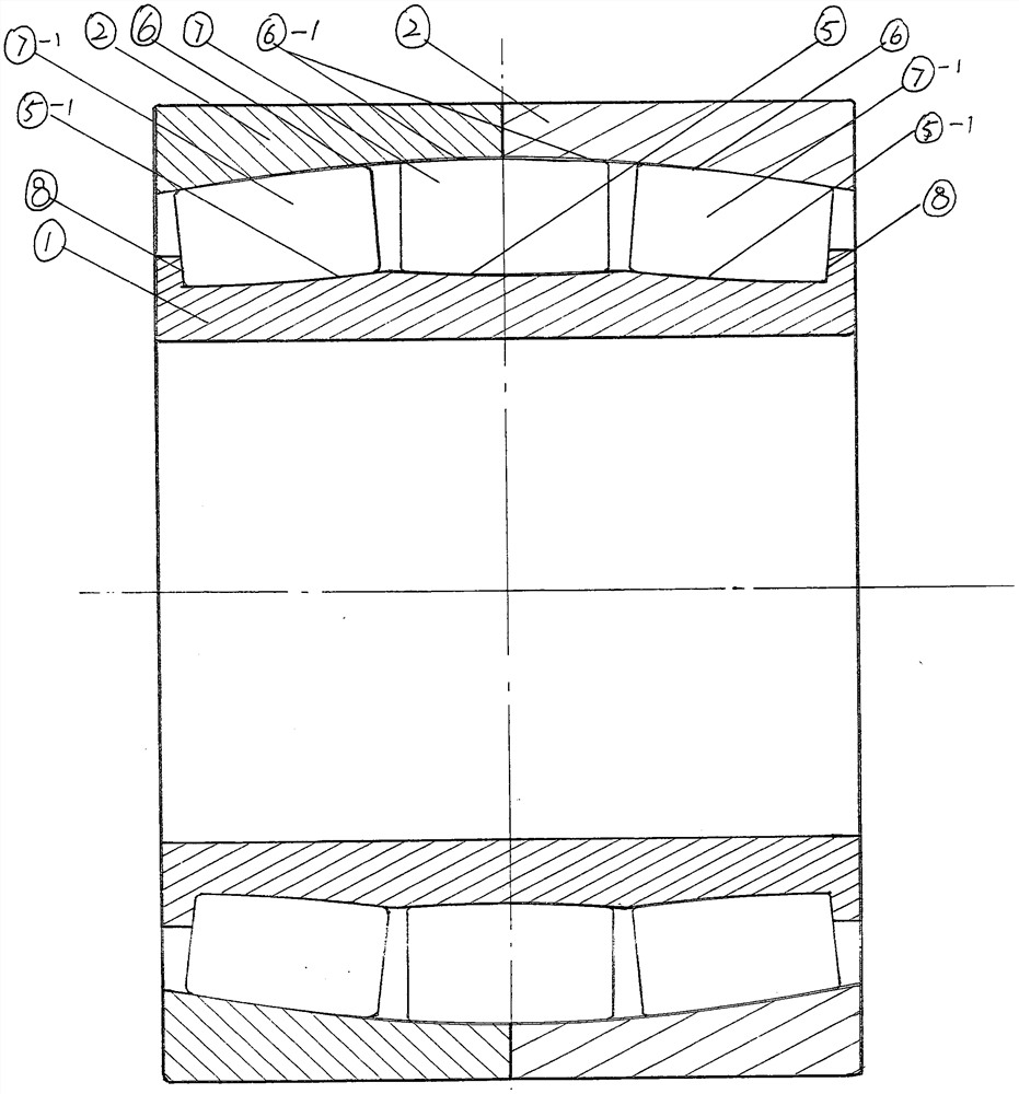
[0055] Such as image 3 The shown super heavy-duty high-speed rail bearing with spherical roller centered balls includes an inner ring 1, two double-half outer rings 2, one ring of symmetrical spherical rollers 7 and two rings of asymmetrical spherical rollers 7 -1, the inner circumferences of the two double-half outer rings 2 are each provided with a spherical roller track 6. After the two double-half outer rings 2 are concentrically combined, their inner circumferences form a shared spherical roller track 6-1. The radius of curvature of the spherical roller track 6-1 is larger than the radius of the circumferential track of the bearing roller, so that the axial section of the shared spherical roller track 6-1 has an elliptical structure,

[0056] The inner ring 1 is provided with a central spherical roller track 5 in the middle of the axial distance of the outer circumference at the angle line perpendicular to the bearing axis line, and a symmetrical spherical roller 7 is ar...


PUM


Abstract

The invention relates to a super-overloading high-speed rail bearing, and provides the super-overloading high-speed rail bearing with a spherical roller center ball. The super-overloading high-speed rail bearing with the spherical roller center ball comprises an inner sleeve ring, two double half outer sleeve rings, a circle of convex symmetrical roller and two circles of convex asymmetrical rollers, wherein after the two double half outer sleeve rings are coaxially combined, inner circumferences of the two double half outer sleeve rings form a shared spherical roller orbit, the curvature radius of the shared spherical roller orbit is larger than the radius of a roller circumference orbit, and the axial cross section of the shared spherical roller orbit is of an ellipsoidal structure; a circle of spherical roller orbit is arranged in the middle of the outer circumference of the inner sleeve ring perpendicular to a bearing axis; an axis of a spherical roller arranged in the orbit is symmetrical to the bearing axis; a circle of spherical roller orbit is arranged at each of two ends of the spherical roller orbit; the two rows of spherical roller orbits and a vertical axis of the bearing form an angle of 1-20 degrees; and the inner sleeve ring is combined with the shared spherical roller orbit arranged on the inner circumferences of the double half outer sleeve rings through threerows of spherical roller so as to form a spherical roller bearing structure of an ellipsoidal spherical roller orbit. According to the super-overloading high-speed rail bearing with the spherical roller center ball, by utilizing the convex symmetrical roller center ball, the carrying capacity is improved, the friction force is reduced, and a joint load is carried by convex asymmetrical roller bearings arranged at two ends of the center ball, so that the super-overloading high-speed rail bearing is formed.

Description

technical field [0001] The invention relates to high-speed rail bearings. Background technique [0002] 1. At present: the high-speed rail bearings manufactured by developed countries in the world are still tapered roller bearings manufactured on the basis of advanced bearing materials and technology. Research data show that there are many fatal defects in the mechanical structure of tapered roller bearings, such as: [0003] (1) Stress concentration: The stress concentration at the end of the tapered roller bearing roller is a congenital fatal defect that cannot be cured, and its common main hazard is to cause raceway indentation and peeling; [0004] (2) The rollers are easy to skew: The biggest congenital fatal defect of tapered roller bearings is that the uneven force on the contact line of the rollers during the rotation can easily make the rollers skew, which directly leads to indentation, peeling, and retention of the ring raceway. The cracking of the frame or the cr...

Claims


Application Information

Patent Timeline
IPC IPC(8): F16C19/18F16C19/38F16C19/49F16C33/58
CPCF16C19/18F16C19/38F16C19/49F16C33/583
Inventor 孟萍
Owner 孟萍
Why Eureka
Try Eureka